00193463-01.pdf - 第179页
User Manual SIPLAC E S-25 HM 5 Station extensions Software Vers ion SR.503.xx 04/2002 U S Edition 5.4 PCB b arcode 179 Æ The barco de mode op erating state is show n in the s tatus display of the men u window . This op- …
5 Station extensions User Manual SIPLACE S-25 HM
5.4 PCB barcode Software Version SR.503.xx 04/2002 US Edition
178
5.4.6 Configuring the PCB barcode reader
The PCB barcode reader is configured using barcode labels. The retrofit kit contains the program
for defining these labels. 5
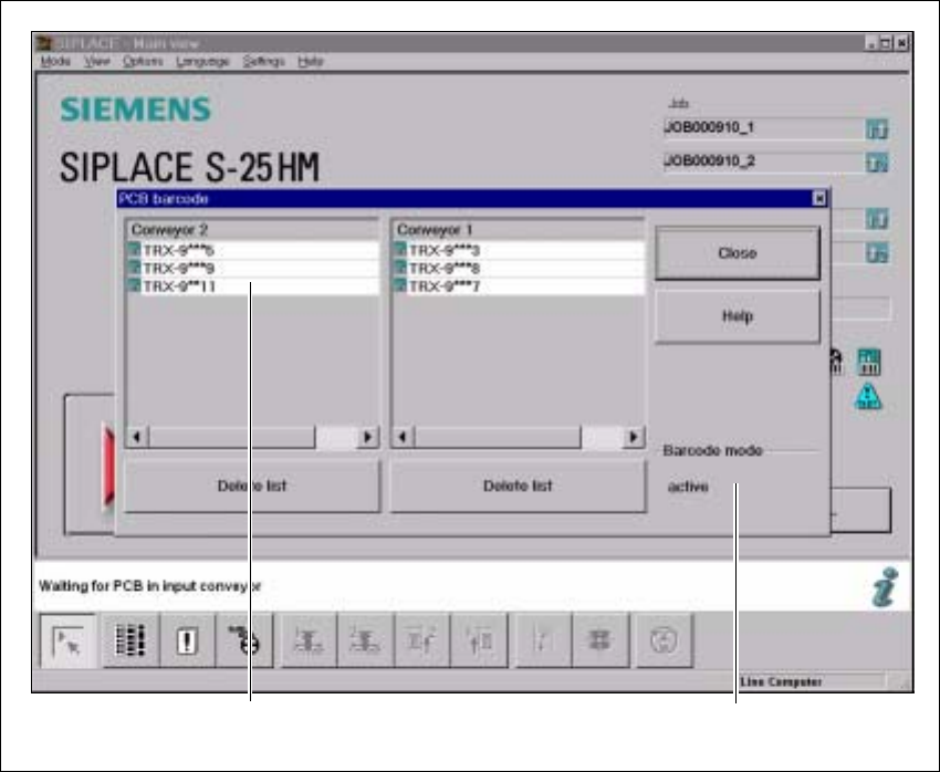
5.4.7 Displaying the PCB barcode
This menu is used to display in a list box the last barcode to be read by the PCB barcode reader.5
The box also indicates if the barcode was read incorrectly, a start signal was received, the wrong
format was identified or no data was available. 5
Æ Select the PCB barcode submenu under Options from the menu bar.
.
Fig. 5.4 - 4 Displaying the PCB barcode
(1) List box
(2) Status display
Æ To delete the list, click on the Delete list button.
15
2 5

User Manual SIPLACE S-25 HM 5 Station extensions
Software Version SR.503.xx 04/2002 US Edition 5.4 PCB barcode
179
Æ The barcode mode operating state is shown in the status display of the menu window. This op-
erating state is activated and deactivated by the line computer.
PLEASE NOTE
This menu is only active if the PCB barcode option is installed, and has been activated in the ma-
chine options. 5

5 Station extensions User Manual SIPLACE S-25 HM
5.5 Ceramic substrate centering Software Version SR.503.xx 04/2002 US Edition
180
5.5 Ceramic substrate centering
5.5.1 General
The ceramic substrate can be centered either mechanically or optically. 5
With optical centering, the fiducials can be detected with either normal or oblique lighting. 5
5.5.2 Possible centering types
The following centering types for ceramic substrates can be entered in the transport type machine
data (REAL.MA). 5
5.5.3 Mechanical centering
5.5.3.1 General
Mechanical substrate centering is used to lock ceramic substrates firmly in position in the X and
Y directions in such a way that the material is not damaged. Ceramic substrates can also be
placed right up to the edge. 5
5.5.3.2 Changing the ceramic substrate on the PCB
Æ Disconnect the air line and power cable (see point 1 in Fig. 5.5 - 1).
Æ Remove the ceramic substrate centering (see point 2 in Fig. 5.5 - 1).
Æ Detach the base of the ceramic substrate centering unit (see point 3 in Fig. 5.5 - 2).
Æ Remove the three clamping parts (see point 4 in Fig. 5.5 - 1), and fit the standard guide at this
point.
Æ Fit the hold-down bracket (see point 5a and 5b in Fig. 5.5 - 1).
Æ Adjust the size of the PCB (see point 6 in Fig. 5.5 - 1).
Æ Use the SITEST program to edit the transport type (see table in Section 5.5.2) in the machine
data.
Transport type Centering
4 Mechanical substrate centering with normal lighting
5 Oblique lighting only with Y axis PCB clamping unit
6 Mechanical substrate centering with oblique lighting