00193463-01.pdf - 第139页
User Manual SIPLAC E S-25 HM 4 Component han dling Software Version SR.503.xx 04/2002 US Edition 4.2 Technical data for the feeders 139 4.2.1 1 Surf t ape feeder 4.2.1 1.1 Overview Y ou will n eed the surftape feeder to …
4 Component handling User Manual SIPLACE S-25 HM
4.2 Technical data for the feeders Software Version SR.503.xx 04/2002 US Edition
138
4.2.10 Bulk case feeder
4
Fig. 4.2 - 10 Bulk case feeder
Item no. 00142318-xx
Width 30 mm
Tracks per feeder 2
Maximum number of feeders 2 x 20
Magazine capacity Approx. 5000
Feeding rails 0603 / 0.45 mm high Item no. 00142321-xx
0603 / 0.80 mm high Item no. 00142322-xx
0805 / 0.45 mm high Item no. 00142323-xx
0805 / 0.60 mm high Item no. 00142324-xx
0805 / 0.85 mm high Item no. 00142325-xx
0805 / 1.25 mm high Item no. 00142326-xx
Minimelf Item no. 00142328-xx
Cycle time < 80 ms
Main power supply 30 VDC
Compressed air supply 2.0 bar + 0.3 bar
User Manual SIPLACE S-25 HM 4 Component handling
Software Version SR.503.xx 04/2002 US Edition 4.2 Technical data for the feeders
139
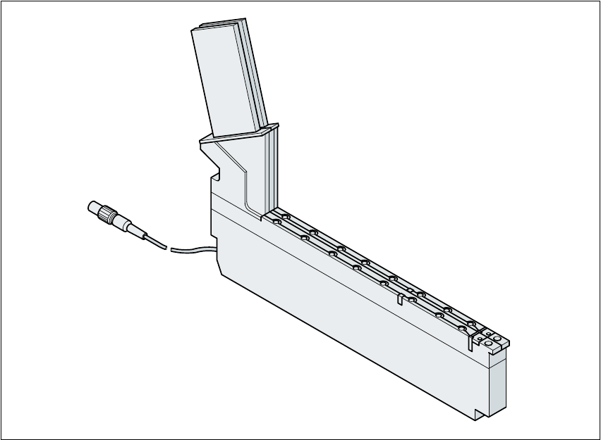
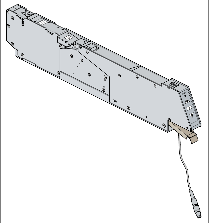
4.2.11 Surftape feeder
4.2.11.1 Overview
You will need the surftape feeder to supply the components in order to insert bare dies. Feeder
versions are available for 8 mm tapes and 12 or 16 mm tapes. 4
Fig. 4.2 - 11 Surftape feeder
Item no. 00141180-xx 4
Use of the surftape feeder is described in the feeder operating instructions. 4
4

4 Component handling User Manual SIPLACE S-25 HM
4.2 Technical data for the feeders Software Version SR.503.xx 04/2002 US Edition
140
4.2.11.2 Technical data
4
4
4
4
4
4
4.2.11.3 Parameters for the surftape feeders
The parameters for the surftape feeders can be modified on the line computer.
4
Tape widths 8/12/16 mm
Recommended tape and component
sizes
8 mm: 1 x 1 mm – 2.3 x 2.3 mm components
12 mm: 2.3 x 2.3 mm - 5 x 5 mm components
16 mm: 3.8 x 3.8 mm -9.5 x 9.5 mm components
Packaging accuracy of the bare die on
the surf tape
Bare die sizes up to 2.3 x 2.3 mm: +/- 100 µm, 6
σ
Bare die sizes over 2.3 x 2.3 mm: +/-200 µm, 6 σ
(in relation to the center of the pocket)
Required distance between the edges of
the bare dies to the tape pocket Min. 0.4 mm
Pusher needle Single or triple needle depending on the die size
Tape material Metric
Tape standard IEC 286-3, DIN-IEC-286, EIA 481 and JIS C 0806
Tape reel diameter 7" to 15"
Feeder footprint 1 track on the component feeder table