JO-072-006_w.pdf - 第89页
4-4 AKBEG-ID T o enlarge the image, press the [Enlarge] button in the "Master Setting" window . T o get the original size, press the [Return] button. Fig. D5 (5) Press the "ZERO/ABS" switch of the mic…
4-3
AKBEG-ID
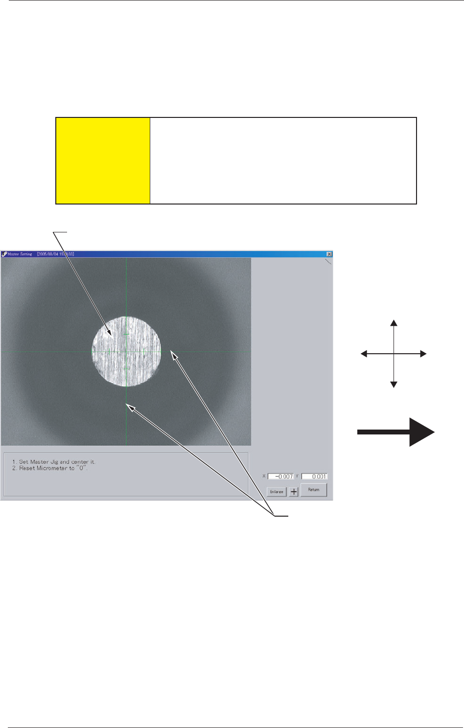
(3) The "Master Setting" window opens. Conrm that a crosshair is dis-
played in the window.
When no crosshair is displayed, press the [+] button in the window
to make it appear.
(4) Move the micrometer until the center of the crosshair is aligned
with the pin center of the pickup position master.
CAUTION
Do not give a strong shock to the micrometer by
hitting against human body or an object. Otherwise,
the micrometer may be damaged, resulting in
inaccurate adjustment of the feeder's component
pickup position.
X (-)
Y (-)
X (+)
Y (+)
Pin of Pickup Position Master
Crosshair
Direction of Tape Feed
Fig. D4 "Master Setting" Window
0508-001
1. Registration of Master Position (Jig Origin Adjustment)
4-4
AKBEG-ID
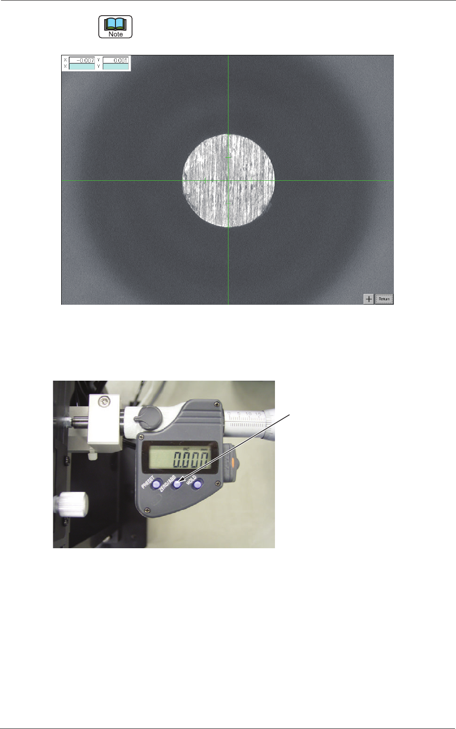
To enlarge the image, press the [Enlarge] button in the "Master Setting" window.
To get the original size, press the [Return] button.
Fig. D5
(5) Press the "ZERO/ABS" switch of the micrometer to reset the indi-
cated value of the micrometer head to "0.000".
"ZERO/ABS" Switch
Fig. D6 Micrometer
0508-001
1. Registration of Master Position (Jig Origin Adjustment)
4-5
AKBEG-ID
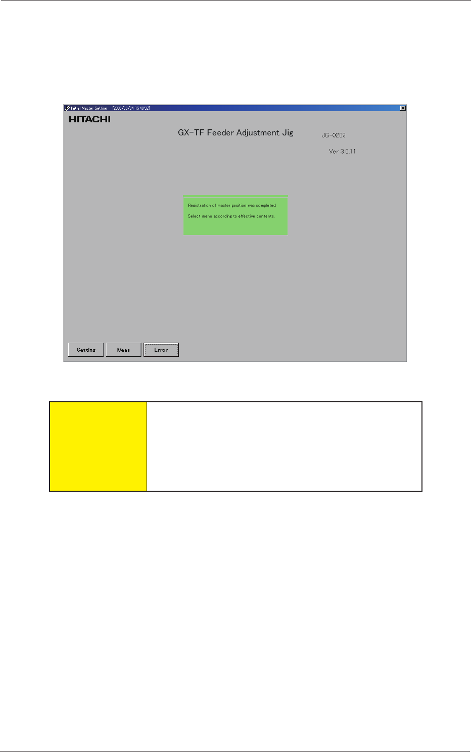
(6) Press the [Return] button in the "Master Setting" window.
(7) The following message appears in the "Initial Master Setting" win-
dow, indicating that the registration of the master position is com-
pleted.
Detach the pickup position master from the jig.
Fig. D7
CAUTION
Be sure to slowly lift the pickup position master to
detach from the jig. Otherwise, the pickup position
master will come off abruptly and collide with the
camera used to capture an image of the pickup
position. The camera may be damaged.
0508-001
1. Registration of Master Position (Jig Origin Adjustment)