JO-072-006_w.pdf - 第98页
4-12 AKBEG-ID (6) Put the light shielding jig (accessory part) in the cover tape tension detection photosensor section and set the photosensor in the "E/NR" mode. Ref.: E/NR (Light Emitted and Not Received) Lig…
4-11
AKBEG-ID
WARNING
If you wear a pacemaker, do not handle the tape
feeders.
The tape feeders use permanent magnets. The
pacemaker may be affected by the magnetism and a
serious accident will result.
CAUTION
•
Be sure not to drop any tape feeder. Otherwise,
your feet will get hurt or the feeder may be
damaged.
Carefully handle each tape feeder and never drop any.
•
When you install a tape feeder on the adjustment
base, avoid getting your ngers caught between
the end of the feeder and the adjustment base and
the connectors.
•
The master tapes are made of a thin metal.
Carefully handle the tapes to avoid cutting your
nger with the tape edges.
CAUTION
Conrm that the hook at the end of the tape feeder
is securely engaged and the suppressor is not set
aoat.
630 128 0127
00-0115-
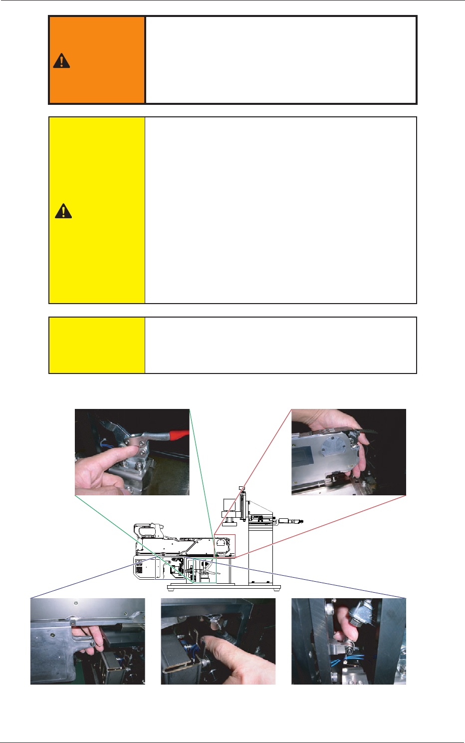
Feeder Fixing Areas
Toggle Clamp Between End of Feeder and Adjustment Base
Fig. D12
0508-001
2. Feeder Measurement
4-12
AKBEG-ID
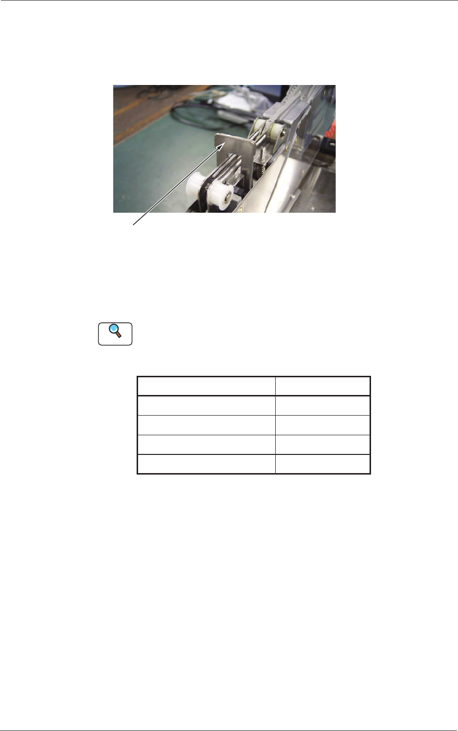
(6) Put the light shielding jig (accessory part) in the cover tape tension
detection photosensor section and set the photosensor in the "E/NR"
mode.
Ref.:
E/NR (Light Emitted and Not Received)
Light Shielding Jig
This may look different from the light shielding jig
(accessory part).
Fig. D13
(7) Set the feeder feeding pitch for the measurement as follows
Reference
Refer to "4.2.2 Feeding Pitch Setting Operation" in the instruction manual "Tape
Feeders for GXH Series" for how to set the feeding pitch.
Table D3
Models Feeding Pitches
GT-0808*, GD-0808* 2 mm
GT-12160, GD-12160 4 mm
GT
-24320, GD-24320 4 mm
GT-44560, GD-44560 4 mm
0508-001
2. Feeder Measurement
4-13
AKBEG-ID
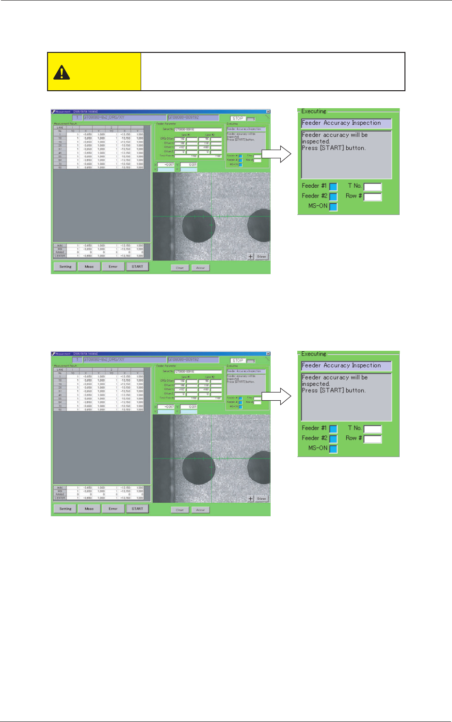
(8) Lower the toggle clamp of the jig to x the tape feeder.
The parameters are read.
CAUTION
Avoid getting your nger caught in the toggle clamp
while fastening the tape feeder to the jig.
Fig. D14
(9) After the reading is completed, the window is changed as follows.
Conrm the following.
Fig. D15
0508-001
2. Feeder Measurement