00197469-02_SM_Twin_Kunde_EN.pdf - 第13页
2 Overview of the modules Service Manual SIPLACE TwinStar (Twin, Twin HF, Twin VHF) 07/2020 13 2 Overview of the modules Fig.3: Overview of the Twin heads 1. Pick&Place module THK R2 [03097485‑xx] (Twin) Pick&…

1 Introduction
1.5 Tools required, measuring equipment and materials
12 Service Manual SIPLACE TwinStar (Twin, Twin HF, Twin VHF) 07/2020
2 Overview of the modules
Service Manual SIPLACE TwinStar (Twin, Twin HF, Twin VHF) 07/2020 13
2 Overview of the modules
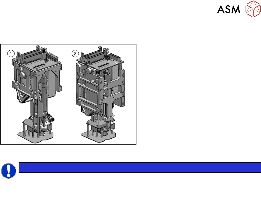
Fig.3: Overview of the Twin heads
1. Pick&Place module THK R2
[03097485‑xx] (Twin)
Pick&Place module High Force R2
[03097486‑xx] (TwinHF)
2. VHF Twin module [03096701‑xx]
(TwinVHF)
NOTICE
Exemplary description
All descriptions are examples. The procedure is the same for other head types than the
ones shown. Any relevant differences will be mentioned explicitly.
2 Overview of the modules
2.1 SIPLACE Twin / Twin HF
14 Service Manual SIPLACE TwinStar (Twin, Twin HF, Twin VHF) 07/2020
2.1 SIPLACE Twin / Twin HF
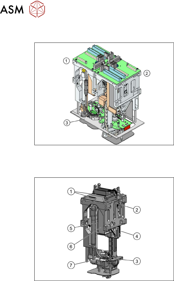
Fig.4: Twin / Twin HF
●
Pick&Place module THK R2
[03097485‑xx] (Twin)
●
Pick&Place module High Force R2
[03097486‑xx] (Twin HF)
The Twin / twin HF consists of two
Pick&Place modules.
1. Module 1
2. Module 2, rotated by 180° compared to
module 1
3. Camera lens hood (depends on
machine)
2.1.1 Overview of parts for Twin / Twin HF
Fig.5: Overview of parts for Twin / Twin HF
1. Slots for TQM167 SIPLACE Embedded
module (only on older machines)
2. Head main board
3. Trick and feather unit
4. Z axis incremental encoder
5. Return unit
6. Pressure control valve
7. Stopper for return unit