00197469-02_SM_Twin_Kunde_EN.pdf - 第70页
5 Boards and cables 5.1 Replacing the head main board 70 Service Manual SIPLACE TwinStar (Twin, Twin HF, Twin VHF) 07/2020 Further information The head main board is mounted directly on the P&P module. The head main …
5 Boards and cables
5.1 Replacing the head main board
Service Manual SIPLACE TwinStar (Twin, Twin HF, Twin VHF) 07/2020 69
5.1.1 Head main board C600
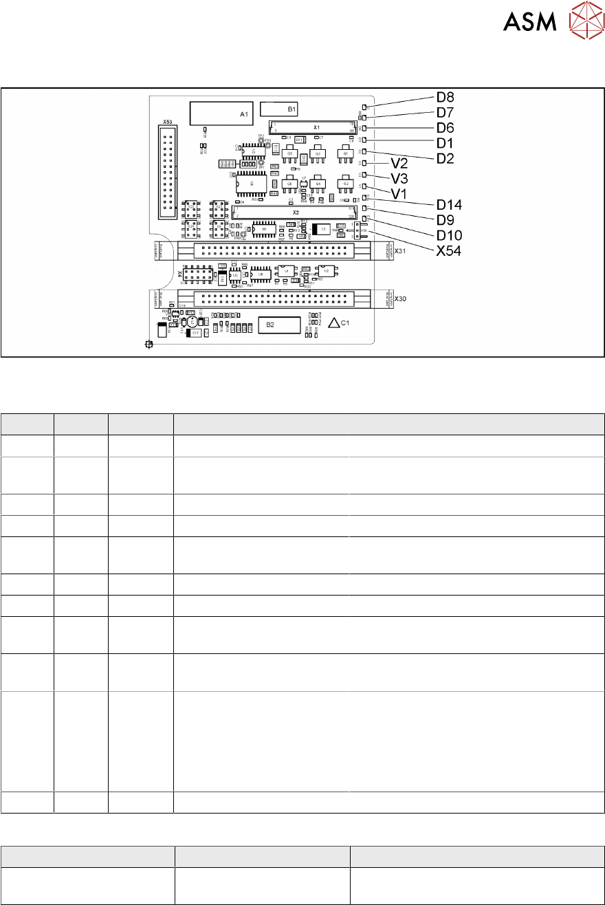
Fig.128: Head main board C600 [00352833-xx]
LEDs [00352833-09]
LED Color Status Signal name Description
D1 YE OFF Z_PRESSURE Not used
D2 YE ON/OFF Z_CLAMPING ON: Z axis clamping activated
OFF: return unit in upper position
D6 GN OFF Z_REFERENCEBERO Not used
D7 GN ON - Return cylinder moved out
D8 GN OFF Q3_OUT Flashes shortly when the return unit is
moved out
D9 GN OFF Q1_OUT Not used
D10 GN ON VCC_PROPVALVE +24VDC for vacuum generator OK
D14 RD OFF SPI_PROP_VALVE_ALAR
M_N
ON: vacuum generator defective
V1 GN ON Z_TEMPERATURE-
SENSOR
Z motor temperature OK
V2 GN ON/OFF V_OUT Signalizes the 15V power supply for the
D axes track signals
OFF: Jumper X54 set to ON for the old
force measuring board
ON: Jumper X54 set to OFF for the new
force measuring board
V3 GN ON V_OUT +15VDC for the D axes track signals
Jumper [00352833-09]
Jumper Status Description
X54 OFF New force measuring board: LED V2
ON
5 Boards and cables
5.1 Replacing the head main board
70 Service Manual SIPLACE TwinStar (Twin, Twin HF, Twin VHF) 07/2020
Further information
The head main board is mounted directly on the P&P module. The head main board is connected
to the basis adapter (SIPLACE SX/DX-Series) or head adapter (SIPLACE X‑Series) with two flat
ribbon cables.
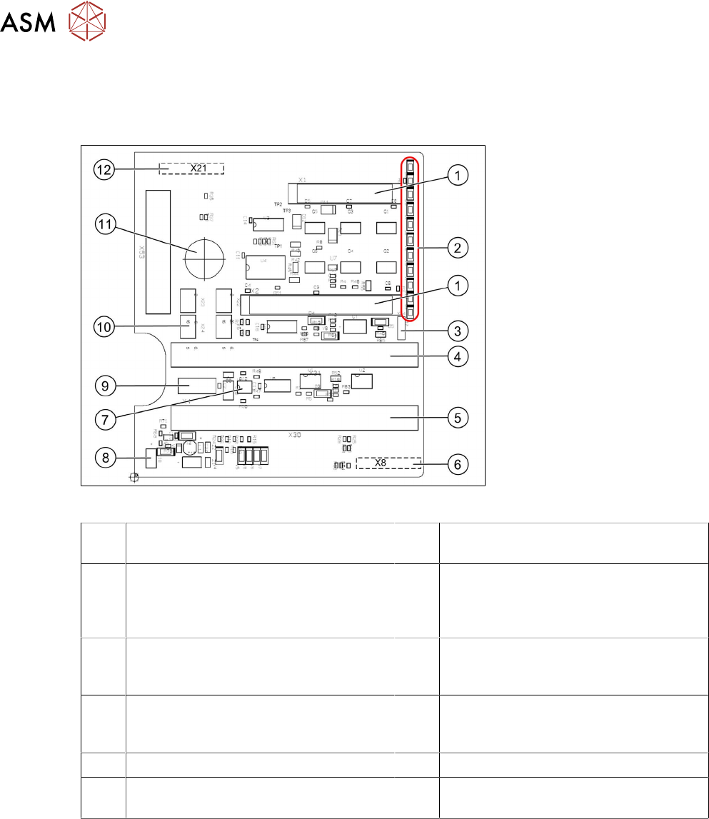
Fig.129: Head main board C600 [00352833-xx]
1 Two connectors for the 16 bit CAN bus
processor (not used for X/D1/D3)
2 LEDs (see below)
3 X54 jumper
currently set to ON
with the new force measuring board set
to OFF (see LED V2/V_SP)
4 Connector to the head adapter flat rib-
bon cable
5 Connector to the head adapter flat rib-
bon cable
6 X8: Flex cable (signals: track signals D
axis, motor voltage Z axis/D axis, Z tem-
perature, SPI bus)
7 EEPROM stores the head specific data
(head exchange, reference run)
8 Power supply 15 V for the D axis track
signals (currently deactivated via the
jumper)
9 X4: connector track signals Z axis 10 Connector pneumatic valve (retract unit)
11 Hole for pneumatic hose to the vacuum
generator
12 X21: connector for vacuum generator
5 Boards and cables
5.1 Replacing the head main board
Service Manual SIPLACE TwinStar (Twin, Twin HF, Twin VHF) 07/2020 71
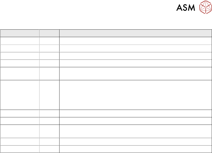
To (2) LEDs (description sequence downwards)
LED Color Description
D8 Green Off – return unit is moved out – LED shines briefly
D7 CLAMP Green On - display showing that the return cylinder has been moved out.
D6 BERO Green Off - without function (previously: proximity switch, Z axis top)
D1 PRESSURE Yellow Off - without function (Z pressure)
D2 CLAMP Yellow On – Z axis clamping
Off – return unit is in "top position"
V2/V_SP Green Shows the 15V power supply for the D axis track signals.
Off – when jumper setting is ON and with old force measuring board.
On – when TwinHead has new force measuring board, the 15V is
regulated on the head main board i.e. the jumper must be set to OFF
and the LED is on.
V3 15V_ Green On – 15V for the D axis track signals
V1 TEMP Green On - Z axis motor temperature is OK
D14 ALARM Red Off - Alarm output for the vacuum generator
On - Vacuum generator defective
D9 PRESSURE Green Off - without function (Z pressure)
D10 24V+ Green On – 24V for vacuum generator OK