00197469-02_SM_Twin_Kunde_EN.pdf - 第16页
2 Overview of the modules 2.2 SIPLACE Twin VHF 16 Service Manual SIPLACE TwinStar (Twin, Twin HF, Twin VHF) 07/2020
2 Overview of the modules
2.2 SIPLACE Twin VHF
Service Manual SIPLACE TwinStar (Twin, Twin HF, Twin VHF) 07/2020 15
2.2 SIPLACE Twin VHF
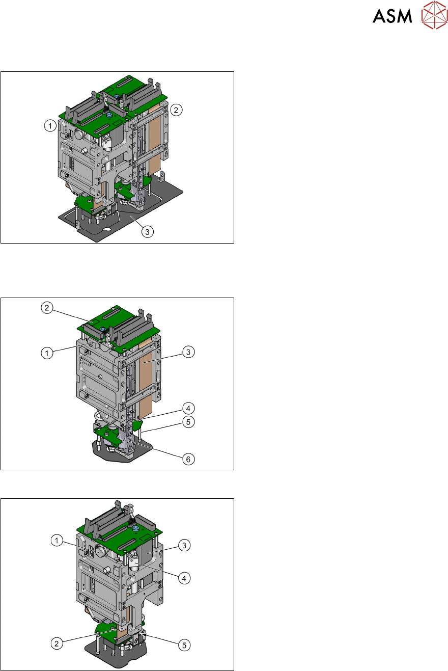
Fig.6: SIPLACE Twin VHF
VHF Twin module [03096701-xx]
The SIPLACE Twin VHF always consists of
two VHF Twin modules.
1. Module 1
2. Module 2
3. Camera lens hood (depends on
machine)
2.2.1 Overview of parts for Twin VHF
Fig.7: Overview of parts for SIPLACE Twin VHF
1. Strain relief for Z encoder
2. Head main board
3. Control cable
4. Z axis incremental encoder
5. Connector clamping piece
6. Linear guide Z axis
Fig.8: Overview of parts for SIPLACE Twin VHF
1. Air filter assembly
2. Hose and flat ribbon guide for VHF
Twin
3. Digital pressure control valve
4. Return unit
5. Return unit buffer

2 Overview of the modules
2.2 SIPLACE Twin VHF
16 Service Manual SIPLACE TwinStar (Twin, Twin HF, Twin VHF) 07/2020
3 Return unit
3.1 Replacing the return unit buffer
Service Manual SIPLACE TwinStar (Twin, Twin HF, Twin VHF) 07/2020 17
3 Return unit
3.1 Replacing the return unit buffer
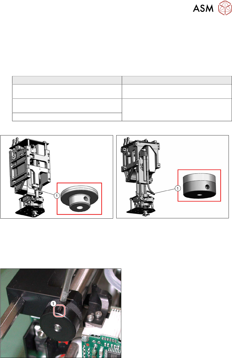
Parts
●
Select the required spare part:
Head type Spare part
Twin VHF module [03096701‑xx] Return unit buffer assembly VHF
[03091163‑xx]
Pick&Place module High Force R2
[03097486‑xx]
Return unit buffer assembly [03004759-xx]
Pick&Place module THK R2 [03097485‑xx]
Overview
Fig.9: Return unit buffer assembly VHF [03091163‑xx]
Fig.10: Return unit buffer assembly [03004759-xx]
Preparation
► Remove the head from the machine. For details about removing and fitting the placement
head, refer to the service manual for your machine.
Removal
Fig.11: Dismantling the buffer (example of Twin / Twin HF
shown)
► Loosen the side grub screw(1) on the
buffer.
► Unscrew and remove the buffer.