00197469-02_SM_Twin_Kunde_EN.pdf - 第31页
4 Pneumatic and pressure control valve (PRV) 4.3 Calibrating the digital PRV Service Manual SIPLACE TwinStar (Twin, Twin HF, Twin VHF) 07/2020 31 4.3 Calibrating the digital PRV The digital PRV is part of the placement h…
4 Pneumatic and pressure control valve (PRV)
4.2 Replacing the pressure control valve (PRV)
30 Service Manual SIPLACE TwinStar (Twin, Twin HF, Twin VHF) 07/2020
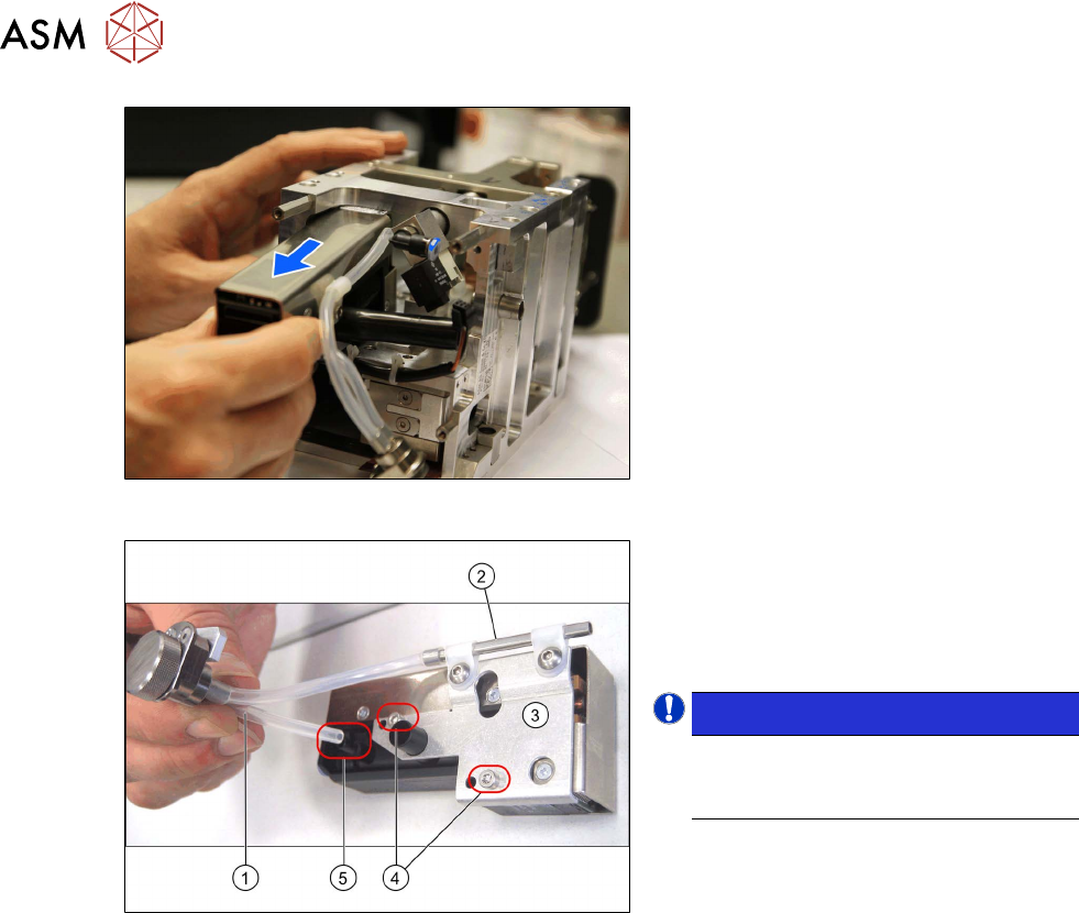
Fig.33: Removing the PRV (Twin VHF)
► Only for Twin / Twin HF:
Pull the PRV and air filter upwards out
of the head together.
Fig.34: PRV mount and air filter
► Pull the silicon hose (1) off the vacuum
connection (5)
on the PRV.
► Remove the two screws(4) fastening
the mount(3)
for the PRV precision
pipe(2)
.
NOTICE!
This holder for the digital PRV has four
fixture holes, of which the two lower
ones (4)
are used.
.
Installation
Installation is performed by following the above instructions in the reverse order. Also observe the
following instructions:
► Fix the two screws fastening the mount to the PRV with a torque of 0.6Nm.
► Fix the two screws fastening the PRV to the head with an Loctite 243 and tighten these with a
torque of 0.6Nm
.
► Make sure that the air filter hoses are not crossed over one another.
► Tighten the cover and the two air filter fastening screws hand-tight.
► Observe the installation instructions in the following sections:
5.1 "Replacing the head main board" [}65]
3.1 "Replacing the return unit buffer" [}17]
► Perform "zero correction" for the pressure control valve.
See also
2 4.1 "Replacing the air filter" [}25]
4 Pneumatic and pressure control valve (PRV)
4.3 Calibrating the digital PRV
Service Manual SIPLACE TwinStar (Twin, Twin HF, Twin VHF) 07/2020 31
4.3 Calibrating the digital PRV
The digital PRV is part of the placement head and generates the vacuum and the air blast for the
pickup and placement process. The zero point calibration of the digital PRV must be performed on
initial startup by the customer and then checked again after replacement of the digital PRV or the
placement head and recalibrated if necessary.
The zero point calibration adjusts the pressure control valve to the ambient pressure.
4.3.1 Zero point calibration of the pressure control valve
NOTICE
From SW706 this function is run during automatic calibration of the Twin Head.
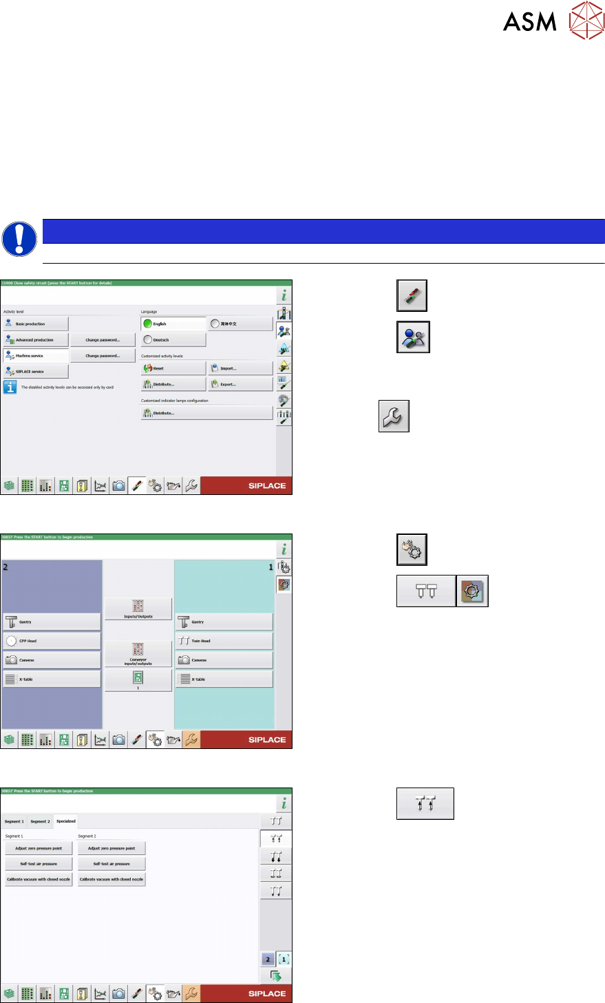
Fig.35: Select operator level
► Select the button.
► Select the button.
► Switch over to the operator level Machine
service.
ð The button will be shown.
Fig.36: Sensors and Functions menu
► Select the button
► Select the button.
► Select the placement head.
Fig.37: Vacuum Functions menu
► Select the button.
► Go to the Specialized tab.
► Select the Zero pressure adjustment but-
ton for the relevant Segment
(Twin mod-
ule).
► Follow the next instructions on the screen.
4 Pneumatic and pressure control valve (PRV)
4.3 Calibrating the digital PRV
32 Service Manual SIPLACE TwinStar (Twin, Twin HF, Twin VHF) 07/2020
4.3.2 Calibrating the Closed Vacuum
NOTICE
From SW706 this function is run during automatic calibration of the Twin Head.
Tools
●
Nozzle 518
Calibration
► Pick up the nozzles from the nozzle changer.
NOTICE
Fitting the nozzle
If there are problems picking up nozzles, insert the calibration nozzle manually on the
sleeve. Make sure that the two sleeve adjust pins fit correctly into the nozzle.
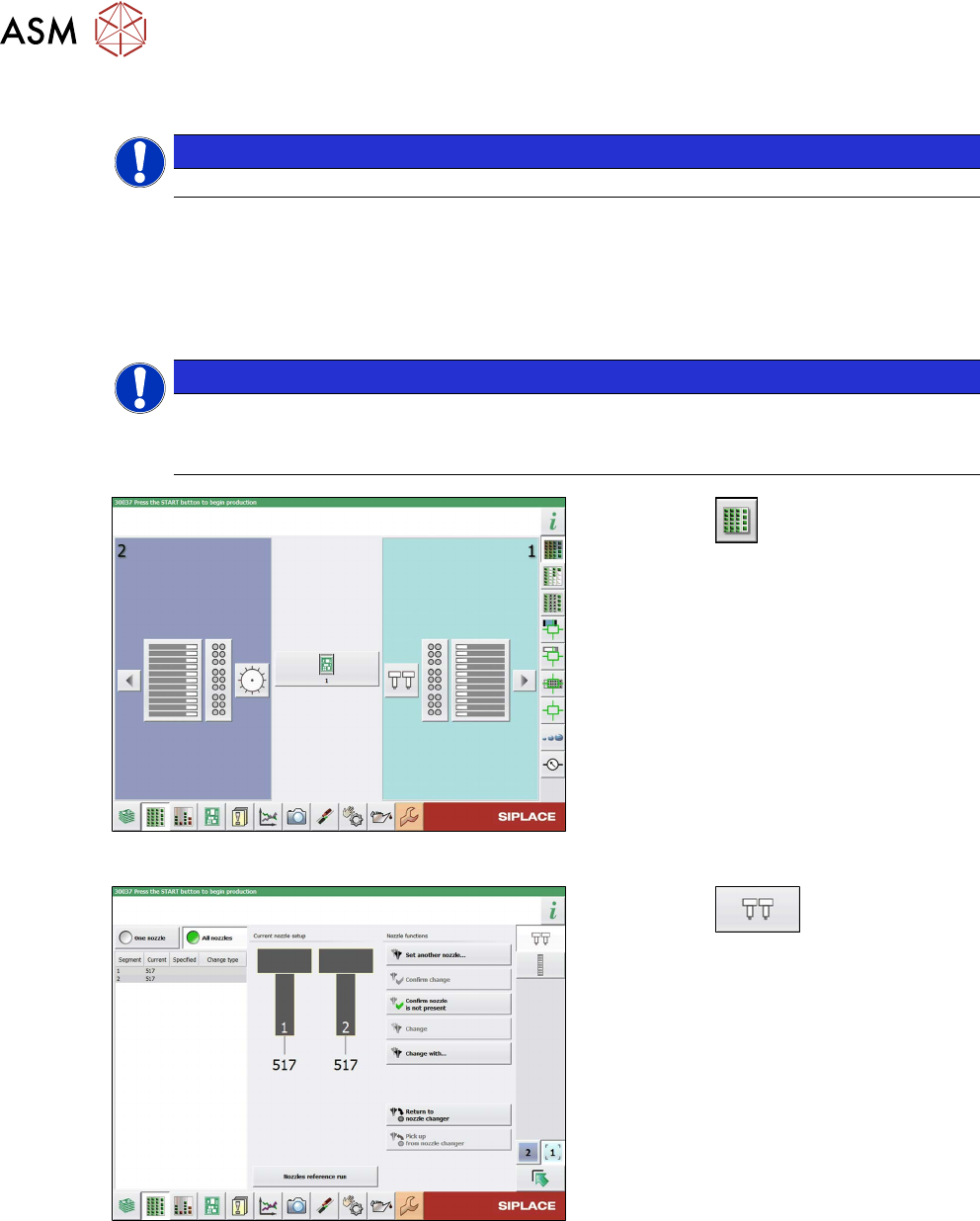
Fig.38: Feeders, Components and Nozzles menu
► Select the button.
► Select the placement head.
Fig.39: Nozzle Configuration menu
► Select the button.
► Select the Set another nozzle... but-
ton....
► Select the calibration nozzle and then
the OK
button.