00197469-02_SM_Twin_Kunde_EN.pdf - 第47页
4 Pneumatic and pressure control valve (PRV) 4.7 Replacing the pneumatic rotary supply Service Manual SIPLACE TwinStar (Twin, Twin HF, Twin VHF) 07/2020 47 4.7 Replacing the pneumatic rotary supply Parts ● Pneumatic rota…
4 Pneumatic and pressure control valve (PRV)
4.6 Replacing the sleeve with ball fixing/seal
46 Service Manual SIPLACE TwinStar (Twin, Twin HF, Twin VHF) 07/2020
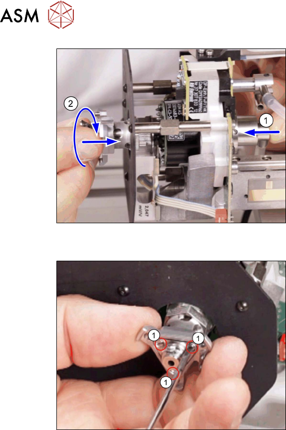
Fig.69: Positioning the sleeve with ball fixing (example of
Twin / Twin HF shown)
► Hold the pneumatic rotary supply(1)
firmly in position, while you press the
sleeve with ball fixing onto the pipe with
a turning motion (2)
.
Fig.70: Fastening the sleeve with ball fixing (example of
Twin / Twin HF shown)
► Fasten the sleeve with ball fixing with
three screws(1)
(hand-tight).
► Fit the buffer.
3.1 "Replacing the return unit buffer" [}17]
Follow the removal instructions in reverse order for further installation. Also observe the following
instructions:
► After fitting the elbow version 1, check the pneumatic rotary supply for centricity.
4.4.1.1
"Replacement of elbow version 1" [}38]
4 Pneumatic and pressure control valve (PRV)
4.7 Replacing the pneumatic rotary supply
Service Manual SIPLACE TwinStar (Twin, Twin HF, Twin VHF) 07/2020 47
4.7 Replacing the pneumatic rotary supply
Parts
●
Pneumatic rotary supply [03004609Sxx] incl. hose and screws (suitable for all Twin types)
●
Seal for sleeve with ball fixing P&P module [03020698‑xx] (suitable for all Twin types)
When replacing the pneumatic, also replace the seal, as this keeps the rotary supply tube
centrally aligned to the sleeve with ball fixing.
Overview
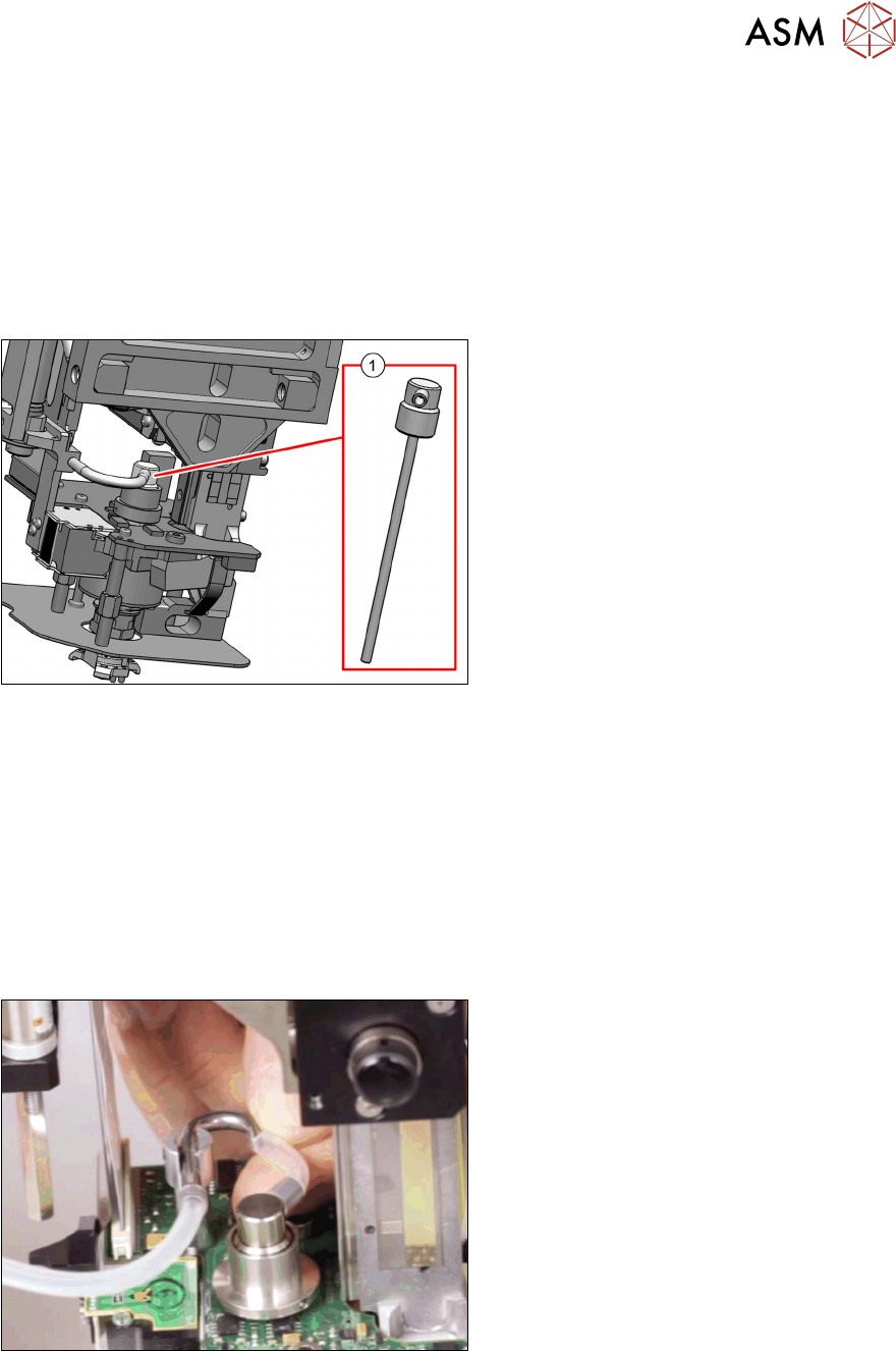
Fig.71: Pneumatic rotary supply
1. Pneumatic rotary supply [03004609-xx]
Preparation
► Remove the head from the machine. For details about removing and fitting the placement
head, refer to the service manual for your machine.
Removal
► Dismantle the buffer.
3.1 "Replacing the return unit buffer" [}17]
► Dismantle the sleeve with ball fixing.
4.6 "Replacing the sleeve with ball fixing/seal" [}43]
Fig.72: Disconnecting the hose
► Disconnect the short hose from the el-
bow.
4 Pneumatic and pressure control valve (PRV)
4.7 Replacing the pneumatic rotary supply
48 Service Manual SIPLACE TwinStar (Twin, Twin HF, Twin VHF) 07/2020
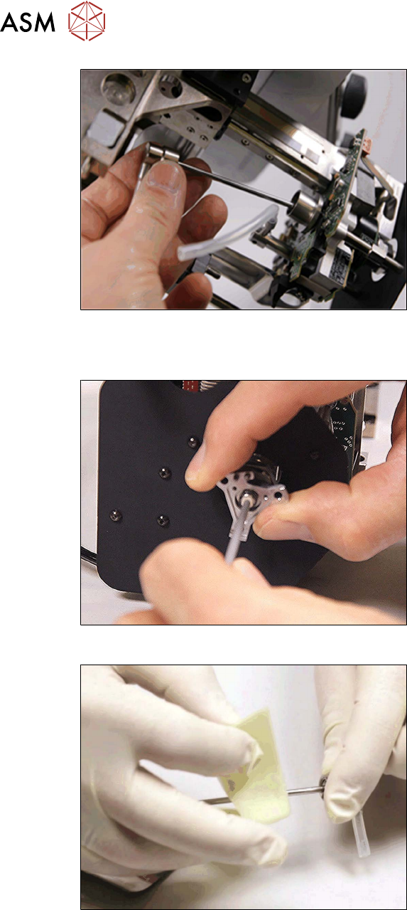
Fig.73: Removing the pneumatic rotary supply
► Pull the pneumatic rotary supply out of
the DP unit.
Installation
Fig.74: Cleaning the pneumatic rotary supply seat 1
► Clean the inside of the DP station shaft
with a cotton swab soaked in isopro-
panol.
Clean both sides as the cotton swab
will not be able to get fully into the guid-
ance from just one side.
Fig.75: Cleaning the pneumatic rotary supply
► Clean the shaft of the pneumatic rotary
supply.