00197469-02_SM_Twin_Kunde_EN.pdf - 第85页
6 Parameter and Calibrations 6.2 Parameters and calibrations SW6xx.x Service Manual SIPLACE TwinStar (Twin, Twin HF, Twin VHF) 07/2020 85 6.2.3.1 Manual calculation of the D axis zero point correction ► Start the SITEST …
6 Parameter and Calibrations
6.2 Parameters and calibrations SW6xx.x
84 Service Manual SIPLACE TwinStar (Twin, Twin HF, Twin VHF) 07/2020
6.2.3 Calibrating the D axis
NOTICE
The exact zero point correction (ZPC) of the D axis is automatically calibrated using a cali-
bration nozzle.
Correct calibration can only be expected if the zero point correction angle differs less than
+/- 5 degrees
from the real value.
► Place the TwinHead calibration nozzle by hand on the sleeve of the appropriate Twin mod-
ule. Make sure that the two sleeve locating pins fit correctly into the nozzle.
► Perform an axis reference run for the D axis.
► Now check the alignment of the nozzle:
The hole drilled on the calibration nozzle must point to the center of the machine and the
nozzle must be aligned parallel to the conveyor.
► Assign the nozzle 516 for the P&P module to be calibrated:
► Start the SITEST program .
► Select the button.
► Select the button.
► Select the required Segment (Twin module) from the list.
► Select Edit.
► Select the 516 nozzle and then select the Accept button.
► Enable Selected segment.
► Select Confirm exchange.
► Start the SITEST program .
► Select the button.
► Select the button.
► Select the Twin module.
► Open the Calibrate zero point of D axis menu.
► When requested to do so by the SW, connect the D axis calibration nozzle.
ð The ZPC will be automatically determined through the angle recognition of the nozzle out-
line. Repeat this procedure until the new value does not deviate more than +/-0.01° from
the previous value.
NOTICE
If the calibration is not successful, you can roughly determine the zero point correction as
described below and enter this value.
6 Parameter and Calibrations
6.2 Parameters and calibrations SW6xx.x
Service Manual SIPLACE TwinStar (Twin, Twin HF, Twin VHF) 07/2020 85
6.2.3.1 Manual calculation of the D axis zero point correction
► Start the SITEST program .
► Select the button.
► Select the button.
► Select the Twin module.
► Select the D axis checkbox.
► Select Positions....
► Set the zero point correction to 0.
► Perform an axis reference run for the D axis.
► Place the TwinHead calibration nozzle by hand on the sleeve of the appropriate Twin mod-
ule. Make sure that the two sleeve locating pins fit correctly into the nozzle.
► Activate the D axis of the Twin module at the axis card.
► Manually rotate the nozzle into the zero position
:The hole drilled on the calibration nozzle must point to the center of the machine and the
nozzle must be aligned parallel to the conveyor.
► In order to display the position of the D axis, open the Z axis menu by checking the checkbox
and then return to D axis
.
► Enter the value shown for the D axis as zero point correction value.
► Reactivate the D axis at the axis board.
► Perform an axis reference run for the D axis
► Now check the position of the nozzle:
The hole drilled on the calibration nozzle must point to the center of the machine and the
nozzle must be aligned parallel to the conveyor.
► Now calibrate the D axis.
6.2.3
"Calibrating the D axis" [}84]
6.2.4 Calibrating the head height
This section is used to determine the Z axis zero point correction.
NOTICE
Make sure that the 517 nozzle is on the TwinHead and has been entered. The zero point
correction, plus the maximum and minimum travel range for the Z axis will be correctly set
after performing Head height
calibration.
► Start the SITEST program .
► Select the button.
► Select the button.
► Select the relevant Twin module.
► Select Calibrating the head height.
6 Parameter and Calibrations
6.2 Parameters and calibrations SW6xx.x
86 Service Manual SIPLACE TwinStar (Twin, Twin HF, Twin VHF) 07/2020
6.2.5 Calibration of vacuum generator on the TwinHead
The vacuum generator is part of a segment on the Twin module (segment) and creates the vacuum
and air blast for the pick up and placement process. The zero calibration of the vacuum generator
should be performed on initial setup at the customer site and after exchanging the vacuum gener-
ator or Twin module.
If you don‘t calibrate the vacuum generator, incorrect threshold values will be used to calculate "No
component on the nozzle or nozzle is dirty".
With the aid of the zero point calibration, the motor of the vacuum generator is positioned in a cent-
ral or neutral position, so that there is no vacuum or air blast on the nozzle.
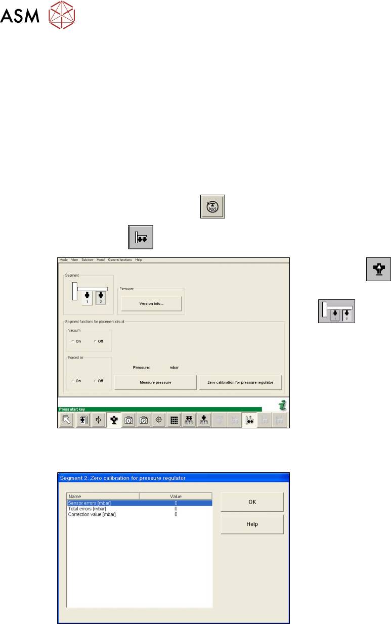
6.2.5.1 Zero point calibration of vacuum generator
► Start the SITEST program .
► Select the button.
Fig.144: SITEST functions for head board
► Select the button.
► Select the Twin module (segment)
.
► Close the nozzle of the appropriate
Twin module (e.g. by sealing it with
your finger tip).
► Select Zero calibration pressure reg-
ulator.
The following dialog field shown the correction value calculated.
Fig.145: Correction values for zero calibration
► Click OK.
The correction value will be accepted. The
pressure controller reference value is there-
fore now calibrated to the ambient pressure.