00197469-02_SM_Twin_Kunde_EN.pdf - 第19页
3 Return unit 3.2 Replacing the Z axis return unit Service Manual SIPLACE TwinStar (Twin, Twin HF, Twin VHF) 07/2020 19 3.2 Replacing the Z axis return unit Read the relevant chapter for details: Twin VHF Fig.14: Return…
3 Return unit
3.1 Replacing the return unit buffer
18 Service Manual SIPLACE TwinStar (Twin, Twin HF, Twin VHF) 07/2020
Installation
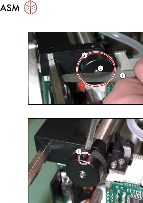
Fig.12: Fitting the buffer (example of Twin / Twin HF shown)
► Screw the new buffer (2)in until the un-
derside is level with the screw (3)
.
Check this e.g with a feeler gauge (1)
.
Fig.13: Fixing the buffer (example of Twin / Twin HF shown)
► Fix the buffer into place with the side
grub screw(1)
.
– Twin VHF: torque 0.3Nm
– Twin / Twin HF: hand-tighten
3 Return unit
3.2 Replacing the Z axis return unit
Service Manual SIPLACE TwinStar (Twin, Twin HF, Twin VHF) 07/2020 19
3.2 Replacing the Z axis return unit
Read the relevant chapter for details:
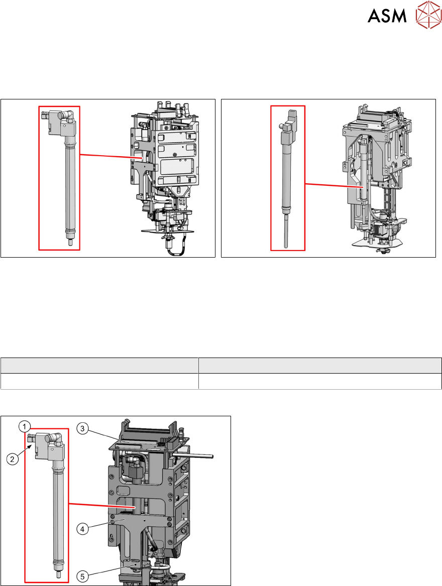
Twin VHF
Fig.14: Return unit VHF Twin [03101743‑xx]
Twin/Twin HF
Fig.15: Z axis return unit [03001361-xx]
For more information, read section 3.2.1 "Return
unit on the Twin VHF" [}19].
For more information, read section 3.2.2 "Return
unit on the Twin/Twin HF" [}21].
3.2.1 Return unit on the Twin VHF
Parts
Head type Spare part
Twin VHF module [03096701‑xx] Return unit VHF Twin [03101743‑xx]
Overview
Fig.16: Overview of return unit (example of Twin HF shown)
1. Return unit
2. Connector/coupling
3. Head main board
4. Mount
5. Grub screw on the mount
Preparation
► Remove the head from the machine. For details about removing and fitting the placement
head, refer to the service manual for your machine.
3 Return unit
3.2 Replacing the Z axis return unit
20 Service Manual SIPLACE TwinStar (Twin, Twin HF, Twin VHF) 07/2020
Removal
► Dismantle the head main board.
5.1 "Replacing the head main board" [}65]
► Dismantle the buffer on the return unit.
3.1 "Replacing the return unit buffer" [}17]
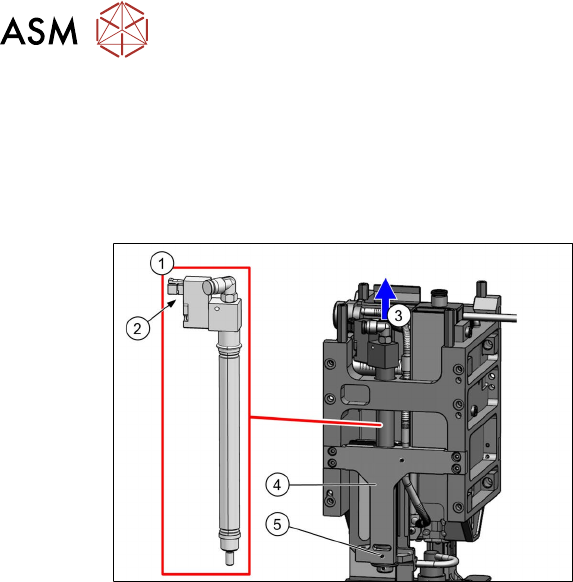
Fig.17: Dismantling the return unit (example of Twin HF
shown)
► Loosen the grub screw (5) on the
mount (4)
.
► Disconnect the plug (2) from the coup-
ling.
► Disconnect the hose from the vacuum
distributor.
► Pull the return unit(1) up(3) and out of
the head.
Installation
► Insert the return unit through the opening in the mount.
► Reconnect the hose and plug.
► Fit the buffer on the return unit.
3.1 "Replacing the return unit buffer" [}17]
► Turn the return unit in the mount so that the cables and plugs do not touch the housing. This
prevents the cables from being damaged during movement.
► Fix the return unit with the grub screw to the mount.
Follow the removal instructions in reverse order for further installation.
Also observe the installation instructions in the following section:
5.1 "Replacing the head main board" [}65]