00197469-02_SM_Twin_Kunde_EN.pdf - 第73页
5 Boards and cables 5.2 Transferring the head specific data Service Manual SIPLACE TwinStar (Twin, Twin HF, Twin VHF) 07/2020 73 5.2.2 Transferring the head specific data (from SW701) After changing the head hardware, th…
5 Boards and cables
5.2 Transferring the head specific data
72 Service Manual SIPLACE TwinStar (Twin, Twin HF, Twin VHF) 07/2020
5.2 Transferring the head specific data
CAUTION
Observe the direction of transfer!
After replacing the PRV, you need to send the valid machine data from the machine to the
new assembly.
The data only needs to be sent from the head to the machine if you have replaced the en-
tire module.
ü As the buttons required are very near to each other, take care that you do not acci-
dentally press the wrong one on the touch screen!
► Make sure you press the correct arrow button. To be on the safe side, select the but-
ton with the mouse.
ð The following section shows the transfer from the machine to the assembly.
► From software version 601 read the section Transmitting the Head-Specific Data (from
SW601).
► From software version 701 read the section Transferring the Head-Specific Data (from
SW701).
5.2.1 Transmitting the head-specific data (from SW601)
► Select the Settings → Access level… menu….
► Switch over to the operating level Service and select OK.
► Start the SITEST program .
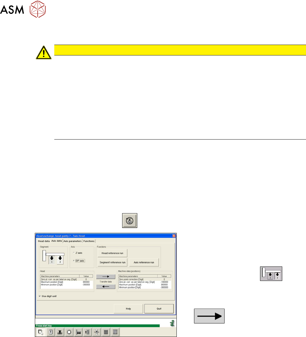
Fig.130: Transmitting the DP axis data
► Select the Settings:head ex-
change:head gantry menu for the rel-
evant gantry.
► Select the Axis data tab.
► Select the Twin module.
► Select the DP axis.
► Transfer the machine data from the
head to the machine data, with the
button.
► Select Close.
5 Boards and cables
5.2 Transferring the head specific data
Service Manual SIPLACE TwinStar (Twin, Twin HF, Twin VHF) 07/2020 73
5.2.2 Transferring the head specific data (from SW701)
After changing the head hardware, the new head data needs to be made available from the head
EPROM of the software:
► Switch on the machine.
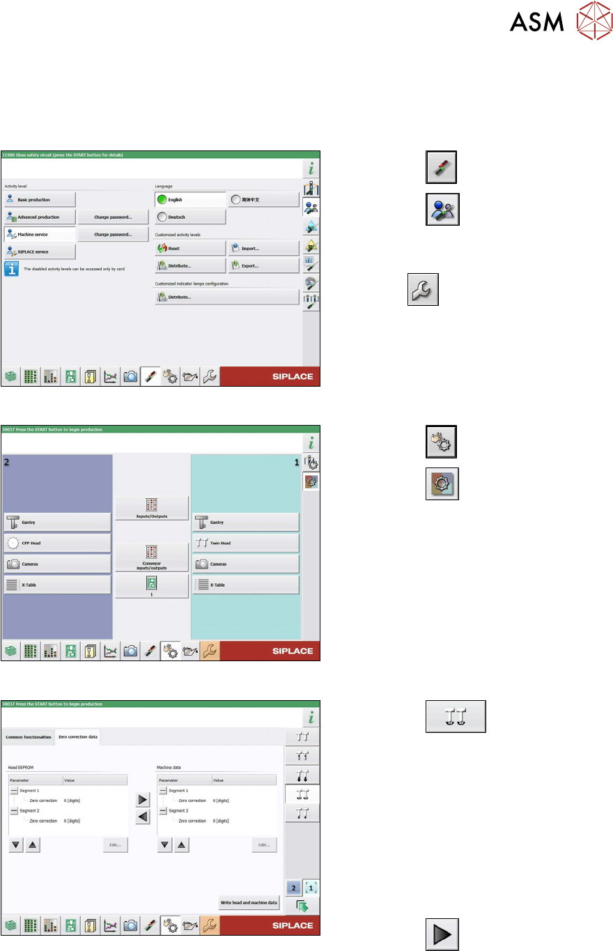
Fig.131: Select operator level
► Select the button.
► Select the button.
► Switch over to the operator level Ma-
chine service.
ð The button will be shown.
Fig.132: Sensors and Functions menu
► Select the button
► Select the button.
► Select the placement head.
Fig.133: Zero point correction data
► Select the button.
► Switch over to the Zero point correc-
tion data(2) tab.
This is where the star axis data can be written
from the head EPROM to the machine data.
Depending on the head type, you can also
write the rotary axis data from the machine
data to the head EPROM.
► In the left section, go to the Zero cor-
rection line and select the relevant
Segment
(Twin module).
► Select the button to move the
value from the head EPROM to the
machine data.
► Select Write head and machine data.
5 Boards and cables
5.3 Replacing the board with cable (Twin HF only)
74 Service Manual SIPLACE TwinStar (Twin, Twin HF, Twin VHF) 07/2020
5.3 Replacing the board with cable (Twin HF only)
Parts
●
Board with cable [03038856-xx]
Overview
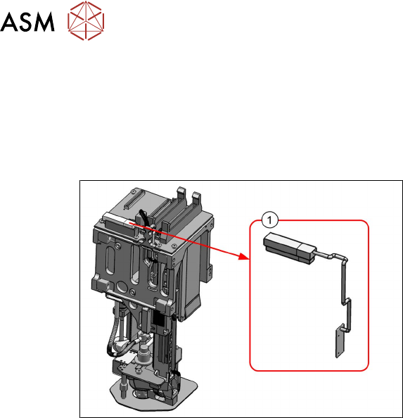
Fig.134: Board with cable
1. Board with cable [03038856-xx]
Preparation
► Remove the head from the machine. For details about removing and fitting the placement
head, refer to the service manual for your machine.
Removal
► Disconnect the cable.
► Unthread the cable as far as the board.
► Remove the fastening screws of the board and then remove the board.
Installation
Follow the removal instructions in reverse order for installation. Also observe the following instruc-
tions:
► Replace any cable ties which you have removed.