00197469-02_SM_Twin_Kunde_EN.pdf - 第50页
4 Pneumatic and pressure control valve (PRV) 4.7 Replacing the pneumatic rotary supply 50 Service Manual SIPLACE TwinStar (Twin, Twin HF, Twin VHF) 07/2020 Fig.79: Hose on elbow version 1 (old) (pipe holder) Fig.80: Ho…
4 Pneumatic and pressure control valve (PRV)
4.7 Replacing the pneumatic rotary supply
Service Manual SIPLACE TwinStar (Twin, Twin HF, Twin VHF) 07/2020 49
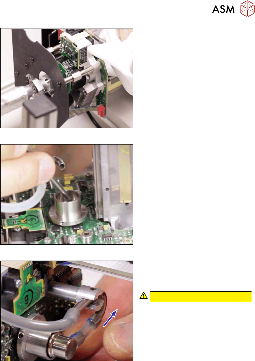
Fig.76: Cleaning the pneumatic rotary supply seat 2
► Clean the seat with compressed air.
Cover the outlet on the other side while
doing this.
Fig.77: Inserting the pneumatic rotary supply
► Insert the new pneumatic rotary supply
into the seat.
Fig.78: Silicone hose 4.5x2.5x26
► Fit the hose from the pneumatic rotary
supply onto the elbow. Connect the
hose so that no tension is applied to
the pneumatic rotary supply.
CAUTION!
The new hose must be mounted abso-
lutely twist-free!
.
4 Pneumatic and pressure control valve (PRV)
4.7 Replacing the pneumatic rotary supply
50 Service Manual SIPLACE TwinStar (Twin, Twin HF, Twin VHF) 07/2020
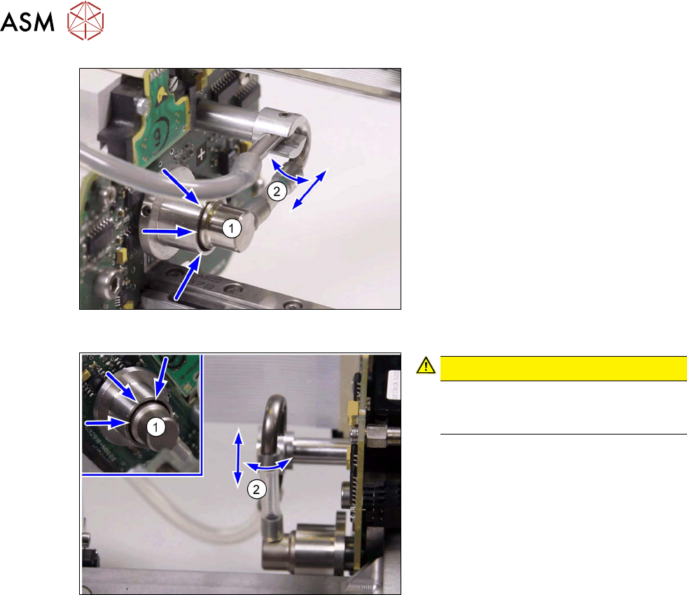
Fig.79: Hose on elbow version 1 (old)
(pipe holder)
Fig.80: Hose on elbow version 2 (new)
(pipe holder and clamp)
The procedure is basically the same for both
elbow versions:
Check the following points:
► The pneumatic rotary supply and the Z
axis must be centered in their guidance
(1)
.
► The short hose must always remain
against the pneumatic rotary supply
stopper.
Press or move the hose on the elbow
to set its position.
Press the hose onto the elbow connec-
tion or away from it, until the axis is po-
sitioned in the center.
► The short hose must also run horizont-
ally(2)
to the elbow, without tension.
CAUTION!
An eccentric position of the Z axis can
alter the balance of forces and lead to
placement errors.
.
► Reconnect the long hose at the top.
► Fit the buffer.
3.1 "Replacing the return unit buffer" [}17]
Follow the removal instructions in reverse order for further installation.
Also observe the installation instructions in the following section:
4.6 "Replacing the sleeve with ball fixing/seal" [}43]
4 Pneumatic and pressure control valve (PRV)
4.8 Replacing the force measuring unit and the trick and feather unit
Service Manual SIPLACE TwinStar (Twin, Twin HF, Twin VHF) 07/2020 51
4.8 Replacing the force measuring unit and the trick and
feather unit
4.8.1 Parts
NOTICE
Since the spring pre-tension needs to be checked and set after replacement, the trick and
feather unit can only be replaced if there is also a Head Care Station available and respect-
ive training has been given. Read the technical information "Approval of spare parts for the
TwinHead Dreheinheit" [DE:TI2018‑11D04] [EN:TI2018‑11E04].
Select the required spare part:
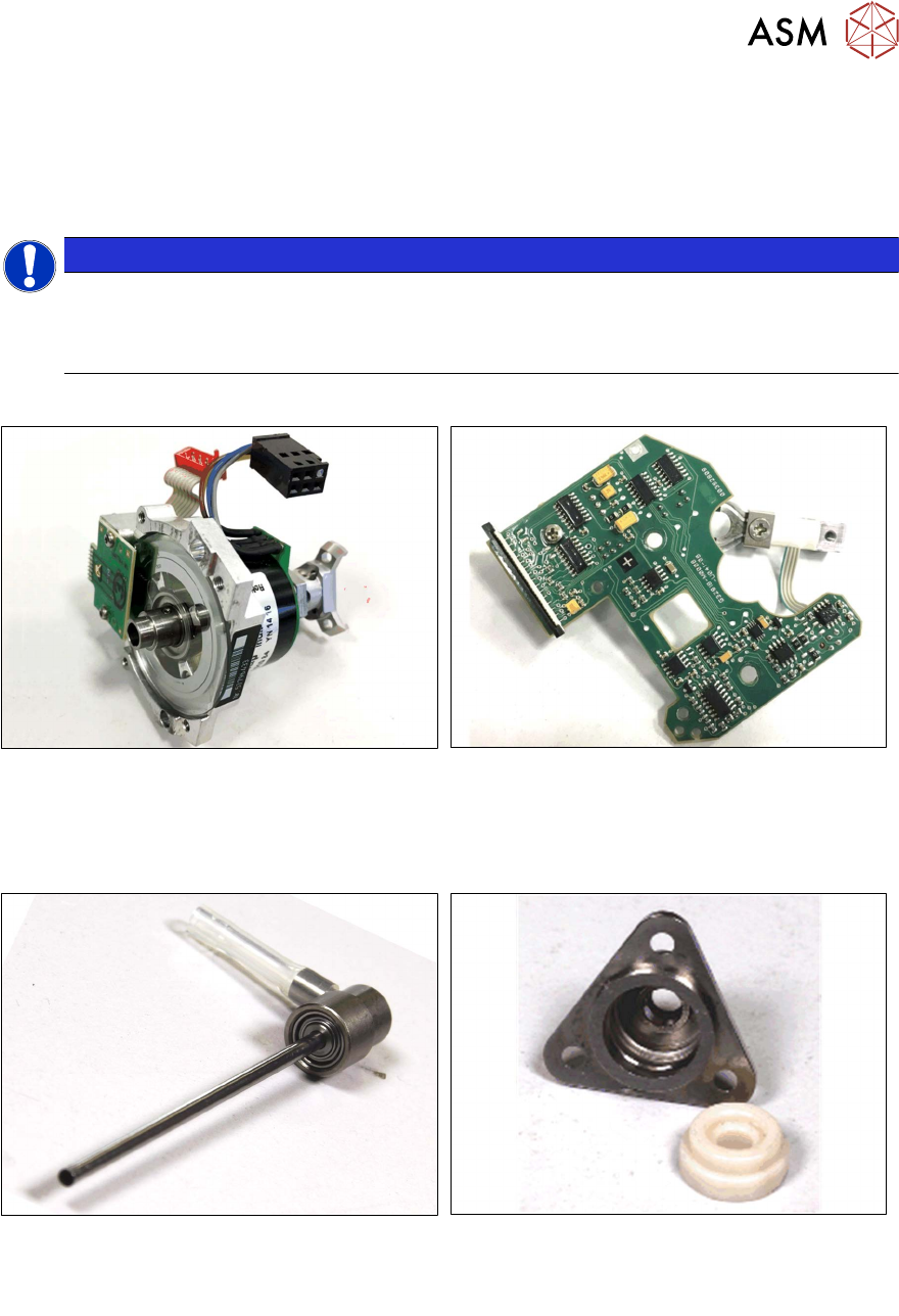
Fig.81: Trick and feather unit P&P module
[03029034Sxx]
When replacing the trick and feather unit, we
also recommend that you replace the pneumatic
rotary supply:
Fig.82: Force measuring unit TwinHead [03012783Sxx]
Fig.83: Pneumatic rotary supply [03004609Sxx]
See also: 4.7 "Replacing the pneumatic rotary
supply" [}47]
Fig.84: Seal, interface P+P-module [03020698‑xx]
See also: 4.7 "Replacing the pneumatic rotary
supply" [}47]