00197469-02_SM_Twin_Kunde_EN.pdf - 第77页
5 Boards and cables 5.5 Replacing the control cable Service Manual SIPLACE TwinStar (Twin, Twin HF, Twin VHF) 07/2020 77 Fig.137: Stopper for return unit and flat ribbon baffle (exam- ple of Twin / TwinHF shown) 1. Sto…
5 Boards and cables
5.5 Replacing the control cable
76 Service Manual SIPLACE TwinStar (Twin, Twin HF, Twin VHF) 07/2020
5.5 Replacing the control cable
Parts
●
Select the correct spare part:
Head type Spare part
Twin VHF module [03096701‑xx] Control cable Twin VHF [03102124‑xx]
Control cable Twin VHF [03102124Sxx] (incl. locking
bracket)
Pick&Place module High Force R2
[03097486‑xx]
Control cable for DP unit, power sensor [03005289Sxx]
Pick&Place module THK R2
[03097485‑xx]
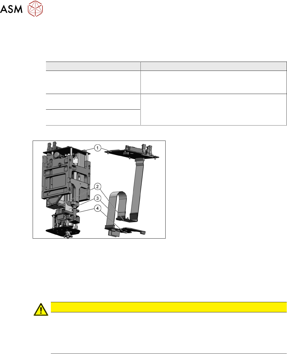
Overview
Fig.136: Overview of control cable (example of TwinVHF
shown)
1. Head main board
2. Flat ribbon holder, Twin VHF
3. Control cable
4. Force measuring unit VHF Twin
Preparation
► Remove the head from the machine. For details about removing and fitting the placement
head, refer to the service manual for your machine.
Removal
CAUTION
Control cable contacts
The control cable and the connector are sensitive parts.
► Make sure you note the correct contact position of the control cables during removal
and installation. The installation position is marked in blue.
► Make sure that the control cable is plugged in straight and is not bent.
► Remove the buffer of the return unit to improve the accessibility.
3.1 "Replacing the return unit buffer" [}17]
► Dismantle the head main board.
5.1 "Replacing the head main board" [}65]
5 Boards and cables
5.5 Replacing the control cable
Service Manual SIPLACE TwinStar (Twin, Twin HF, Twin VHF) 07/2020 77
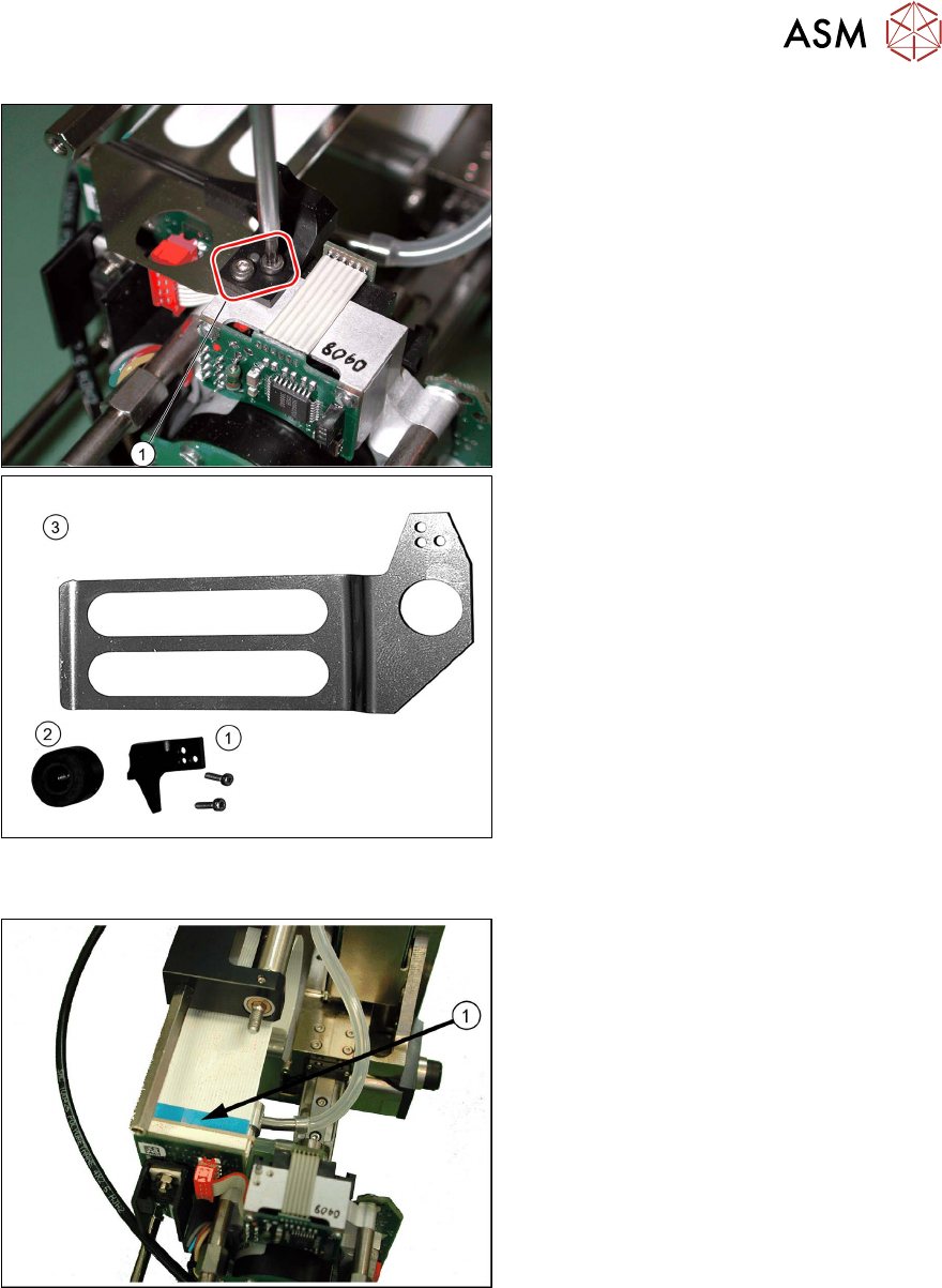
Fig.137: Stopper for return unit and flat ribbon baffle (exam-
ple of Twin / TwinHF shown)
1. Stopper for return unit
2. Return unit buffer assembly
3. Flat ribbon baffle
► Remove the two screws fastening the
stopper(1)
for the return unit.
► Remove the flat ribbon baffle(3).
See also 3.3
"Replacing the hose and
flat ribbon guide (Twin HF only)" [}23]
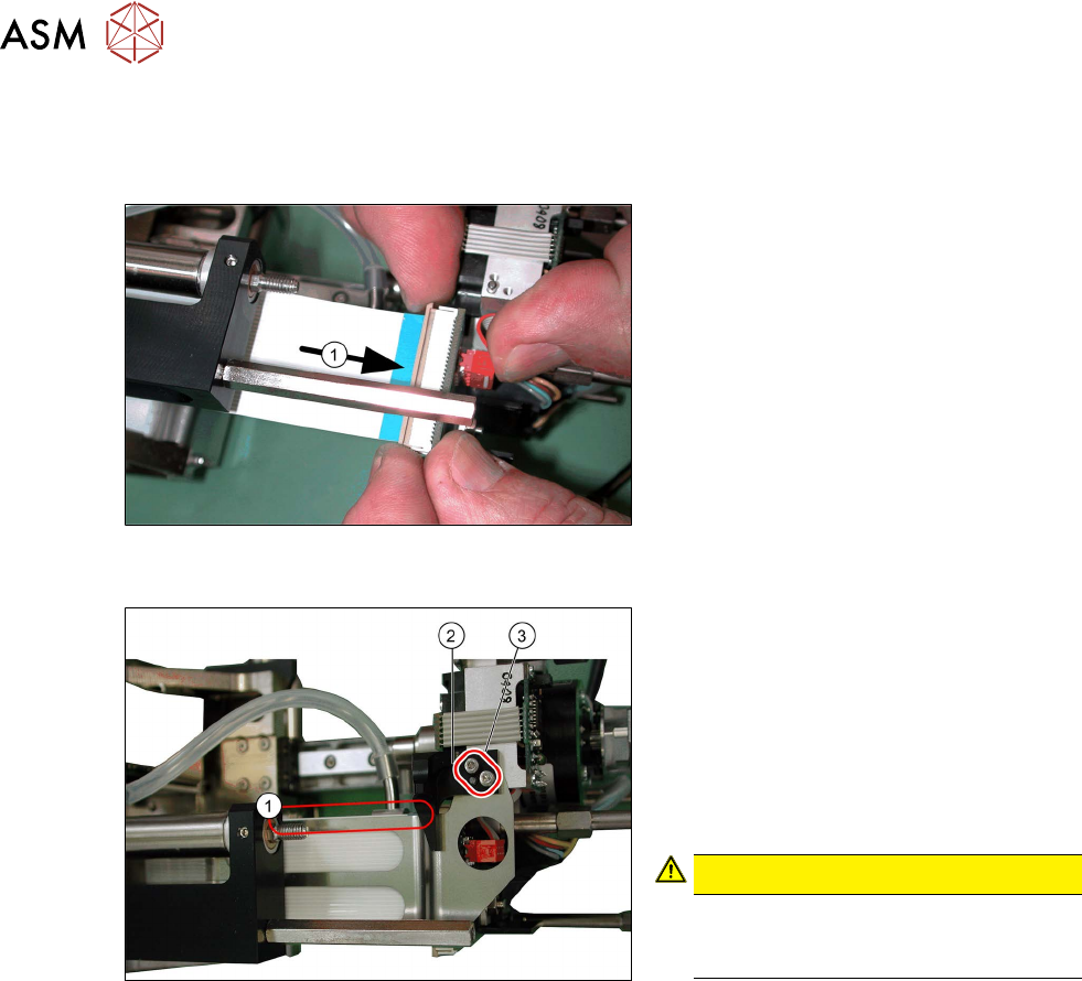
Fig.138: Removing the control cable (example of Twin /
TwinHF shown)
► Release the two locking levers on the
connector upwards and pull the control
cable(1)
carefully off the force meas-
urement board.
► Remove the control cable from the
placement head.
5 Boards and cables
5.5 Replacing the control cable
78 Service Manual SIPLACE TwinStar (Twin, Twin HF, Twin VHF) 07/2020
Installation
► Fit the head main board.
5.1 "Replacing the head main board" [}65]
Fig.139: Attaching the control cable (example of Twin /
TwinHF shown)
► Reconnect the control cable to the
force measuring board(1)
.
Fig.140: Fitting the flat ribbon baffle and stopper for the re-
turn unit (example of Twin / TwinHF shown)
► Place the flat ribbon baffle on to the
control cable.
► Place the return unit stopper (2) onto
the flat ribbon baffle.
► Insert the two screws(3) into the return
unit stopper.
► Align the flat ribbon baffle to the control
cable.
CAUTION!
The flat ribbon baffle and control
cable must run parallel to one an-
other(1)!
.
Follow the removal instructions in reverse order for further installation.
Also observe the installation instructions in the following section:
3.1 "Replacing the return unit buffer" [}17]