00197469-02_SM_Twin_Kunde_EN.pdf - 第24页
3 Return unit 3.3 Replacing the hose and flat ribbon guide (Twin HF only) 24 Service Manual SIPLACE TwinStar (Twin, Twin HF, Twin VHF) 07/2020 Fig.23: Hose and flat ribbon guide ► Remove the hose and flat ribbon guide …
3 Return unit
3.3 Replacing the hose and flat ribbon guide (Twin HF only)
Service Manual SIPLACE TwinStar (Twin, Twin HF, Twin VHF) 07/2020 23
3.3 Replacing the hose and flat ribbon guide (Twin HF only)
Parts
●
Hose and flat ribbon guide for Twin VHF
Overview
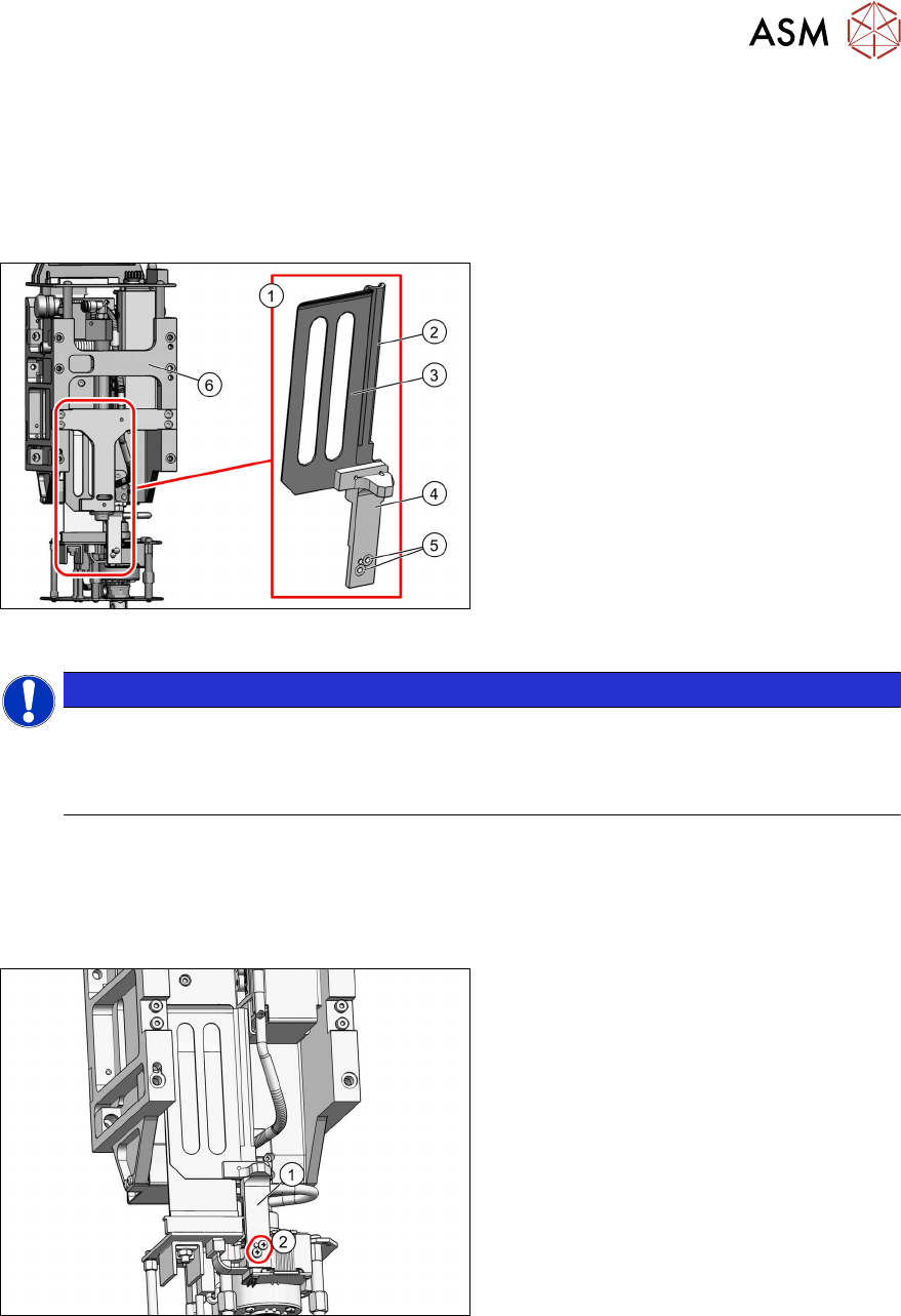
Fig.21: Hose and flat ribbon guide for Twin VHF
1. Hose and flat ribbon guide for Twin
VHF [03100959‑xx]
2. Hose guide
3. Flat ribbon baffle
4. Stopper for return unit
5. Two screws fastening the hose and flat
ribbon guide
6. Return unit mount*
The hose and flat ribbon guide consists of
the hose guide, the flat ribbon baffle and the
return unit stopper.
NOTICE
*Return unit mount
The following section illustrates the Twin VHF without the mount for the return unit. This is
for clarity purposes only. The mount does not need to be removed when dismantling the
hose and flat ribbon guide.
Preparation
► Remove the head from the machine. For details about removing and fitting the placement
head, refer to the service manual for your machine.
Removal
Fig.22: Stopper for return unit
► Remove the two fastening screws(2)
and then remove the return unit(1)
stopper.
3 Return unit
3.3 Replacing the hose and flat ribbon guide (Twin HF only)
24 Service Manual SIPLACE TwinStar (Twin, Twin HF, Twin VHF) 07/2020
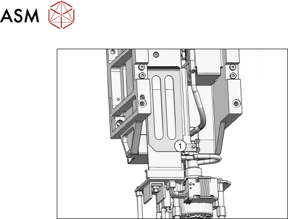
Fig.23: Hose and flat ribbon guide
► Remove the hose and flat ribbon
guide(1)
.
Installation
Follow the removal instructions in reverse order for installation.
4 Pneumatic and pressure control valve (PRV)
4.1 Replacing the air filter
Service Manual SIPLACE TwinStar (Twin, Twin HF, Twin VHF) 07/2020 25
4 Pneumatic and pressure control valve (PRV)
NOTICE
Replacing small parts on the PRV
For details about replacing the small parts on the PRV, please read the job card:
► JobCard Preventive Maintenance SIPLACE TwinHead [DE:00197604‑xx]
[EN:00197603‑xx]
4.1 Replacing the air filter
Parts
●
Air filter assembly [03051420-xx] (suitable for all Twin types)
NOTICE
Head board function state
The head board must have at least FS 09.
Overview
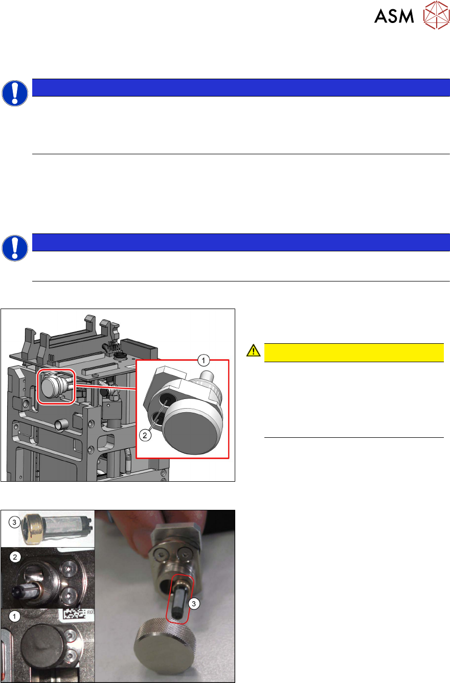
Fig.24: Air filter assembly (example of Twin VHF shown)
1. Air filter assembly
2. Screws fastening the air filter
CAUTION!
Only digital PRV
Do not use an older filter with the new
PRV or a new filter with an analog
PRV. This filter may ONLY be used
with the digital PRV. The hose volume
specified will only work correctly here.
.
Fig.25: Air filter assembly
1. Air filter, closed
2. Air filter, open, with replacement filter
FE50 pulled out halfway
3. Replacement filter FE50 [03047489-xx]
The digital PRV has a precision tube in the
vacuum supply to the nozzle. Between this
tube and the vacuum connection of the PRV
you will find the air filter which protects the
generator from contaminants introduced via
the nozzle (this also applies to the analog
PRV).