00197674-01-UM-E-Series-EN-12-2014.pdf - 第111页
User manual SIPLACE E 3 Technical data and assemblies From software version SC 708.0 12/2014 Edition 3.3 Dimensions an d weight 111 3.3.5 Center of gravity 3.3.5.1 Machine center of gravity 3 Fig. 3.3 - 7 Center of gravi…
3 Technical data and assemblies User manual SIPLACE E
3.3 Dimensions and weight From software version SC 708.0 12/2014 Edition
110
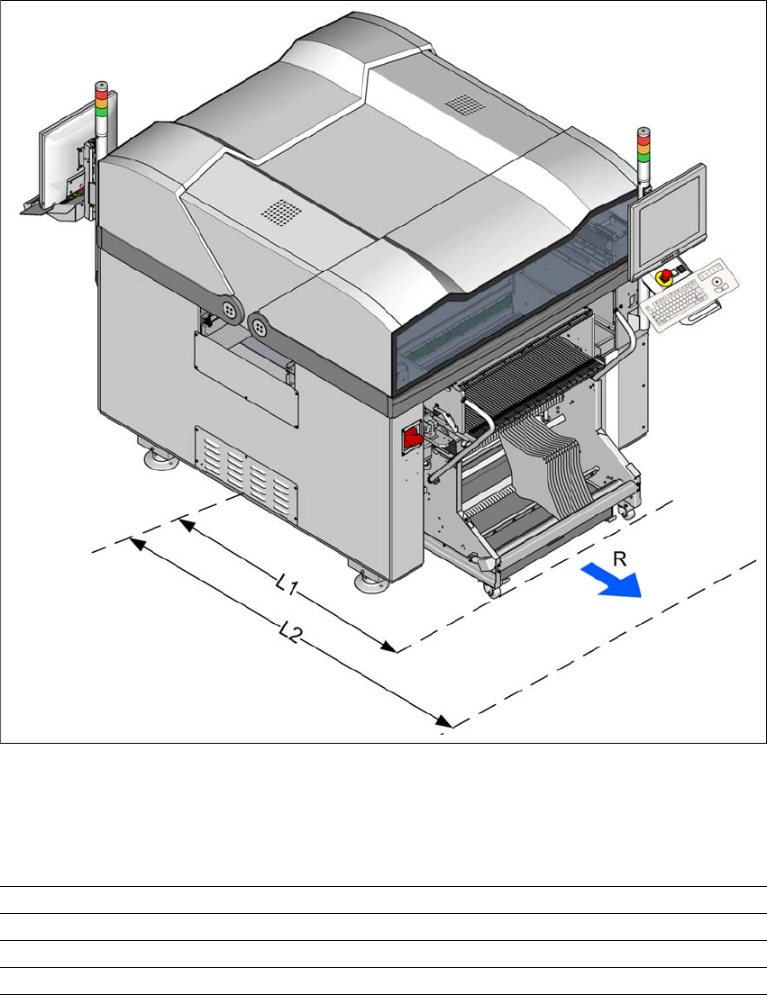
3.3.4 Maneuvering distance for the changeover table
3
Fig. 3.3 - 6 Maneuvering distance for the changeover table on SIPLACE E machine
The maneuvering radii "R" for the changeover table in SIPLACE E machines is:
3
3
Location 1 / Location2
Maneuvering radius R 700 mm
Distance L1: Machine center to outer edge of changeover table 1205 mm
Distance L2: Machine center to wall 1905 mm
User manual SIPLACE E 3 Technical data and assemblies
From software version SC 708.0 12/2014 Edition 3.3 Dimensions and weight
111
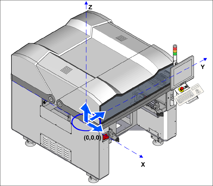
3.3.5 Center of gravity
3.3.5.1 Machine center of gravity
3
Fig. 3.3 - 7 Center of gravity for SIPLACE E machines in millimeters
X coordinate 0 mm
Y coordinate 0 mm
Z coordinate 721 mm
These center of gravity coordinates relate to placement machines with a PCB conveyor height of
900 mm.
3 Technical data and assemblies User manual SIPLACE E
3.4 Overviews of the modules From software version SC 708.0 12/2014 Edition
112
3.4 Overviews of the modules
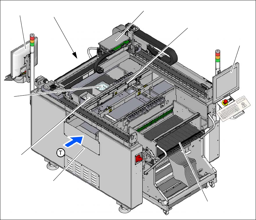
3.4.1 Overview of SIPLACE E double sided assemblies
3
3
Fig. 3.4 - 1 SIPLACE E double sided machine - overview of assemblies
(1) Basic module
(2) Reject bin
(3) Stationary cameras (optional)
(4) Monitor with keyboard (2x) on location 2 (optional)
(5) Location 2 with COT insert, tape cutter, empty tape duct
(6) Gantry with placement head (according to the configuration)
(7) PCB conveyor (single conveyor)
(8) Monitor with keyboard (2x) at location 1
(9) Changeover table at location 1
(T) Direction of PCB transport
(1)
(6)
(7)
(8)
(9)
(4)
(5)
(3)
(2)