00197674-01-UM-E-Series-EN-12-2014.pdf - 第240页
5 Working with the machine User manual SIPLACE E 5.12 Observing displays on the SIPLACE SmartFeeder E From softwa re version SC 708.0 12/2014 Edition 240 5.12.2 Status display –G r e e n : The feeder module i s on standb…
User manual SIPLACE E 5 Working with the machine
From software version SC 708.0 12/2014 Edition 5.12 Observing displays on the SIPLACE SmartFeeder E
239
5.12 Observing displays on the SIPLACE SmartFeeder E
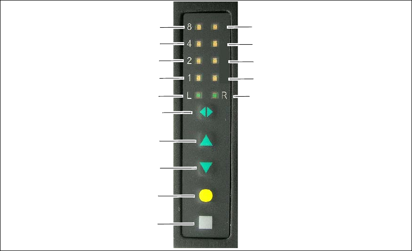
5.12.1 LED display
The SIPLACE SmartFeeder E have a LED display, to indicate the operating states for each track.
5
Fig. 5.12 - 1 Buttons and LED display: example of SIPLACE SmartFeeder 2x8mm E module shown
(1) SET button
(2) FOIL button
(3) BACK button
(4) FORWARD button
(5) Track change button for switching between right and left
(6) LED L left track active
(7) LED 1 mm increment for left track
(8) LED 2 mm increment for left track
(9) LED 4 mm increment for left track
(10) LED 8 mm increment for left track
(11) LED R right track active
(12) LED 1 mm increment for right track
(13) LED 2 mm increment for right track
(14) LED 4 mm increment for right track
(15) LED 8 mm increment for right track
(1)
(2)
(3)
(4)
(5)
(6)
(7)
(8)
(9)
(10)
(15)
(14)
(13)
(12)
(11)

5 Working with the machine User manual SIPLACE E
5.12 Observing displays on the SIPLACE SmartFeeder E From software version SC 708.0 12/2014 Edition
240
5.12.2 Status display
–Green:
The feeder module is on standby and is contained in the current setup.
– Orange:
A warning is being signalized.
– Red:
A malfunction has occurred.
– Off:
The feeder module is not in the current setup.
5
5
5.12.2.1 Status display and possible meanings and and solutions
The following table containing the color of the status display, possible meanings and troubleshoot-
ing measures.
5
PLEASE NOTE
"Status display off" only for feeder modules contained in the setup
The machine controller switches off the status display of any feeder modules not included
in the setup.
The "Status display off" status only occurs when the programming system has preset a
job on the line. This takes some of the work away from the operator since he only has to
watch those feeder modules that are contained in the setup.
PLEASE NOTE
Setup procedure: Activation of the status display for each feeder module
For the actual setup process - no setup information at the station, no job sent from SI-
PLACE Pro to the station/line - the status display on each feeder module is activated after
the setup has been made. The operator is thus informed whether everything is OK.
Status
display
Possible Meaning Solution
Orange The selected function is not permit-
ted when the cover foil is tensioned
(foil rocker is pressed down).
If you wish to carry out that function, remove the foil from
the pair of gear wheels and cut it off to relieve the
pressure on the foil rocker.
Orange 24V supply voltage did not rise
above the switch-on threshold af-
ter switching on
Check the power supply
Red,
flashing
Feeder module software not jump-
ing to the application
Reload the application software
Load feeder module software
Red Feeder module was signaled, but
removal handle is not yet pushed in
Push in the removal handle

User manual SIPLACE E 5 Working with the machine
From software version SC 708.0 12/2014 Edition 5.12 Observing displays on the SIPLACE SmartFeeder E
241
5
5
Red 24V supply voltage rose above the
switch-on threshold after switching
on and was then interrupted
Check the power supply
Red Tape feeder cycle did not end cor-
rectly within the specified time (tim-
eout for the "Feed" function)
Is the tape reel jammed in the container?
Is there a component jammed in the pick-up area be-
tween component tape and component window?
Once the obstacle has been eliminated, use the arrow
keys to restart the conveyor. The feeder module will
move the defective conveyor to the end, and then re-
turned to its position
Red Foil was not tensioned within the
specified time
The foil is probably torn. Insert new foil and tension
Red Foil was not peeled off even
though the tape is moved
The cover foil is probably jammed beneath the pick-up
window and cannot be peeled off correctly
Red Foil motor has locked up Leveling gears blocked by foil? => Remove the foil
Red The data back-up in the EEPROM
was not carried out correctly
Remove the component tape (tape can be moved out by
pressing the arrow keys or pulled out after raising the
pick-up window). Press the SET button to confirm the
error. Then press the yellow button to confirm the refer-
ence run prompt.
Red Data was not read from the EE-
PROM correctly
Red The data back-up in the EEPROM
was not carried out fully
Red Position information is no longer
available for the component tape
drive
Remove the component tape (tape can be moved out by
pressing the arrow keys or pulled out after raising the
pick-up window). Then press the "FOIL" button to start
the reference run.
Red CAN bus error Log off and on again, check the optical fiber interface
Red Parameters were not saved Default parameters are loaded automatically, i.e. the
most recent operator settings are overwritten -> The
settings (e.g. increment) will have to be made again.
Replace the control board if this error occurs frequently.
Red Wrong or incomplete parameters
were saved
Red Can no longer write to boot or ap-
plication memory correctly
Replace the feeder module or control board
Status
display
Possible Meaning Solution
PLEASE NOTE
Remove the component tape before a reference run.