00197674-01-UM-E-Series-EN-12-2014.pdf - 第190页
4 Setting up and commissioning User manual SIPLACE E 4.3 Setting up the machine From software version SC 708.0 12/2 01 4 Edition 190 Hit the feet with a hammer to check th e load-bearing strength o f the machine feet. …
User manual SIPLACE E 4 Setting up and commissioning
From software version SC 708.0 12/2014 Edition 4.3 Setting up the machine
189
4.3.7 Aligning the machine
Measurement is performed at the non clamped lifting table.
Observe the general warnings in section 4.3.1, page 181.
Observe the warnings for transportation of the machine in section 4.3.2, page 182.
For details of tools and equipment, refer to section 4.3.5, page 184.
4
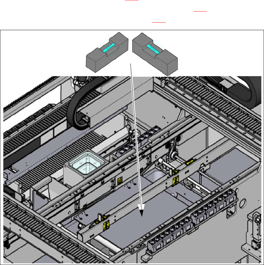
Fig. 4.3 - 5 Adjusting the machine in the X and Y directions - measurement procedure
Place the machine spirit level (measuring accuracy of 0.02 mm) onto the non clamped lifting
table and measure the X and Y directions (1).
Align the machine in the Y direction. The measuring tolerance is 0.10 mm.
Align the machine in the X direction. The measuring tolerance is 0.10 mm.
Check the load-bearing strength of the 4 machine feet. The 4 machine feet must touch the
ground and be evenly loaded.
Tighten the machine feet at the clamping screw to a torque of 130 Nm.
(1)
4 Setting up and commissioning User manual SIPLACE E
4.3 Setting up the machine From software version SC 708.0 12/2014 Edition
190
Hit the feet with a hammer to check the load-bearing strength of the machine feet.
Use the spirit level to ensure that the machine is precisely aligned.
4.3.8 Removing the shipping braces
The shipping braces are attached to the linear guides. Each gantry is fastened with two shipping
braces on the X and Y axes.
Remove all the shipping braces from the gantry axes.
If the SIPLACE machine needs to be transported, always fit the shipping braces back onto
the conveyor.
4.3.9 Removing the corrosion protection from the guide rails
The machines were given a corrosion protection treatment before they were delivered.
4
4
CAUTION
Reduced product life of bearings and guide rails!
If the corrosion protection agent is mixed with the bearing grease on the axes this can
greatly reduce the service life of the bearings and guide rails.
You should therefore remove the corrosion protection from all the axes and bearings
when you traverse the machine axes for the first time during commissioning.
Grease all the axes and bearings with the grease described in the cleaning and
checking instructions.
CAUTION
Risk of damaging bearing grease!
Alcohol will damage the bearing grease in the guide carriages.
When cleaning the guide rails and scales, make sure that alcohol does not get into
the guide trolley.
User manual SIPLACE E 4 Setting up and commissioning
From software version SC 708.0 12/2014 Edition 4.4 Adjusting the changeover table to the PCB conveyor height
191
4.4 Adjusting the changeover table to the PCB conveyor
height
The changeover table can be easily and quickly adjusted to the following PCB conveyor heights:
900 mm and 930 mm 4
950 mm (Option) 4
4
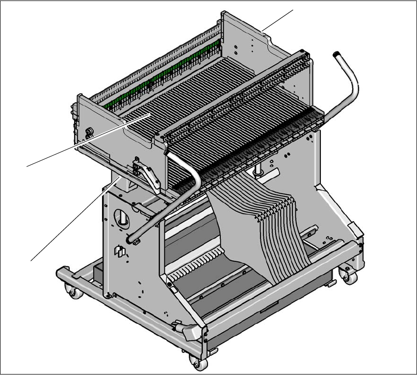
Fig. 4.4 - 1 Changeover table 60
(1) Holes for the transport heights of 900, 930 and 950 mm (behind the cover).
(2) Changeover table
(1)
(2)
(3)