00197674-01-UM-E-Series-EN-12-2014.pdf - 第298页
6 Station extensions User manual SIPLACE E 6.8 Power Supply COT E From software version SC 708.0 12/2014 Ed ition 298 6.8 Power Supply COT E Item no. 03114427-xx Power Supply COT E 6 Fig. 6.8 - 1 Power Supply COT E (1) H…
User manual SIPLACE E 6 Station extensions
From software version SC 708.0 12/2014 Edition 6.7 SIPLACE Preparation Table E
297
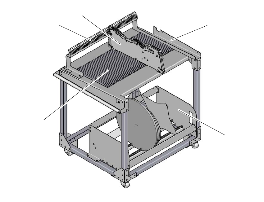
6.7 SIPLACE Preparation Table E
Item no. 03112358-xx SIPLACE Preparation Table E
The SIPLACE Preparation Table E can hold a maximum of 60x SIPLACE SmartFeeder 8 mm E-
with component reel (size 7”, 10”, 13”, 15” & 17”). Feeders can be placed from the top or slid along
the extruded guide profiles. Align each feeder by inserting feeder stop pin into the slots of the
guide plate. SIPLACE Preparation Table E allows SIPLACE PowerAdaptor E to be attached and
detached without tools.
6
Fig. 6.7 - 1 SIPLACE Preparation Table E
(1) Guide profile
(2) Feeder parking unit
(3) SIPLACE SmartFeeder E
(4) Mounting interface for SIPLACE PowerAdaptor E
(5) Tape reel container
(4)
(3)
(2)
(5)
(1)

6 Station extensions User manual SIPLACE E
6.8 Power Supply COT E From software version SC 708.0 12/2014 Edition
298
6.8 Power Supply COT E
Item no. 03114427-xx Power Supply COT E
6
Fig. 6.8 - 1 Power Supply COT E
(1) Harting connection
(2) D-sub connection
(3) Power connection
Harting connection
The PowerSupply COT E provides 25V 10A power output to the E series changeover table (COT)
through the Harting connector. Data transfer is also available through this connection, so commu-
nication with the feeders on the changeover table is possible.
D-sub connection
The D-sub connector is used to connect to the Setup Centre through the CAN bus cable. This al-
lows the user to program and setup the feeders on the changeover table at a remote location,
away from the placement machine.
Power connection
The module comes with 2 power cords for connection to wall outlet. Depending on the type of wall
socket available in your region, please choose the correct power cords. The AC inlet accepts a
wide range of voltages and frequencies (100-240 VAC, 50-60 Hz).
After powering on the module, the green LED on the top cover of the module will light up.
(3)
(2)
(1)
User manual SIPLACE E 7 Cleaning and Checking
From software version SC 708.0 12/2014 Edition 7.1 Cleaning and Checking Intervals Base Machine
299
7 Cleaning and Checking
7
7
7.1 Cleaning and Checking Intervals Base Machine
7
CAUTION
Only qualified personnel
These cleaning and checking tasks may only be carried out by appropriately qualified
personnel.
Caution, as used in this user manual, means that slight injury or damage to equipment
may occur if the caution instructions are not followed.
CAUTION
Filter elements
The cleaning and checking intervals given for inspecting and replacing the filter elements
only apply to the specified compressed air quality (see
Section 3.2.4 on page 103). If
other qualities are used, the intervals should be shortened accordingly.
Cleaning and Checking tasks
Base machine
Duration
[min]
Each
week
Every 3
months
Every 6
months
Every 12
months
– Checking/Cleaning the Cover Fans
3X
– Checking the Fan on the MGCU
5X
– Checking the safety features on machines
4 (6) X
– Checking and Cleaning/Replacing (if required) the
Compressed Air Filter
2X
– Cleaning/Replacing the Head Exhaust Air Filter
1X
– Cleaning the Protective Covers
2X
– Checking/Cleaning/Replacing the Gas Pressure
Shock Absorbers on the Protective Covers
4X