00197674-01-UM-E-Series-EN-12-2014.pdf - 第147页
User manual SIPLACE E 3 Technical data and assemblies From software version SC 708.0 12/2014 Edition 3.8 Feeder module s for SIPLACE E 147 3.8.1.4 Design of the tape feeder modules The two following diagrams show the des…

3 Technical data and assemblies User manual SIPLACE E
3.8 Feeder modules for SIPLACE E From software version SC 708.0 12/2014 Edition
146
3.8.1.3 Manual removal of tantalum capacitors
To prevent tantalum capacitors which were not picked up from causing the tape material to burn
when it is cut, the user interface has been extended to include the option "Stop immediately on
pickup error". This option must be enabled in SIPLACE Pro. On the placement machine, the com-
ponent that was not picked up is paced forward again until it is ready for removal from the com-
ponent tape. The track is deactivated and the operator is sent an error message to remind him to
pick up the tantalum component from the tape. If an alternative track is available, the machine con-
tinues placing. The operator is able to stop the machine, however, and pick up the tantalum com-
ponent. If no alternative track is available and it is not possible to continue placement with other
components, the machine will stop. At this point, the operator can again remove the tantalum com-
ponent and acknowledge the error. Once the operator has restarted the machine, placement is
continued and components are picked up from the track that is now enabled once more.
3
PLEASE NOTE
This software function is also a good idea for expensive components.
Please observe the safety instructions for capacitors on metallic powder basis (see
section 2.5.3
, page 70).
User manual SIPLACE E 3 Technical data and assemblies
From software version SC 708.0 12/2014 Edition 3.8 Feeder modules for SIPLACE E
147
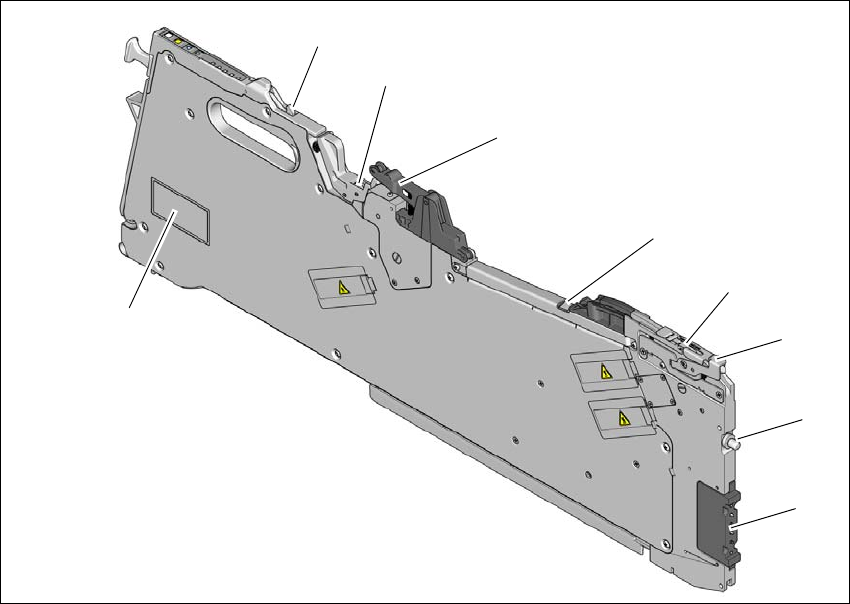
3.8.1.4 Design of the tape feeder modules
The two following diagrams show the design of the tape feeder module for the SIPLACE E.
3
Fig. 3.8 - 1 SIPLACE SmartFeeder E - front view
(1) Pogo-pin interface
(2) "Front" centering pin
(3) Lever for raising the pick-up window in order to thread in and remove the component tape
(4) Pickup window
(5) Tape guide channel outlet
(6) Cover foil rocker
(7) Cover foil packing wheels
(8) Locking latch
(9) Typeplate
(1)
(2)
(3)
(4)
(5)
(6)
(7)
(8)
(9)

3 Technical data and assemblies User manual SIPLACE E
3.8 Feeder modules for SIPLACE E From software version SC 708.0 12/2014 Edition
148
3
Fig. 3.8 - 2 8 mm E tape feeder module - back view
(1) Entry to the tape guide channel with tape spring
(2) Flap on cover foil container
(3) Removal handle, engaged
(4) Status display
(5) Operator panel
(6) Drive motors for the tape conveyor
(7) Front slider guide
(8) Back slider guide
(9) Drive motor for the cover foil packing device
(1)
(2)
(3)
(4)
(5)
(6)
(7)
(8)
(9)