00197674-01-UM-E-Series-EN-12-2014.pdf - 第184页
4 Setting up and commissioning User manual SIPLACE E 4.3 Setting up the machine From software version SC 708.0 12/2 01 4 Edition 184 4.3.3.2 Fitting the operator panels Insert the operato r panel and the indicator lamp…

User manual SIPLACE E 4 Setting up and commissioning
From software version SC 708.0 12/2014 Edition 4.3 Setting up the machine
183
4
4
4
4.3.3 Fitting attached parts
The machine is delivered with the operating panel and monitor, operating panel, keyboard and in-
dicator lamp dismantled. To fit these components, proceed as follows:
– To fit the operator panels see section 4.3.3.2
, page 184
– To fit the monitors on the operator panels see section 4.3.3.3
, page 184
4.3.3.1 Checking and setting the protective cover switch
Check the function of the protective cover switch (see 2.7.2.2 on page 82).
Check whether the protective cover switch is locked. Correct the position of the safety switch
if necessary.
WARNING
Risk of damage due to excessive fork spacing!
Increased fork spacing, which means that the machine is raised at points outside its con-
tact surface, can lead to deformation of the machine frame and cause damage to cables
and lines.
The forks may only be opened to a degree which ensures that they are still within the
contact area of the machine underside (see fig. 4.1 - 3, page 171).
WARNING
Risk of damage due to one-sided loading!
One-sided loading of the machine feet e.g. from tilting the machine, can lead to deforma-
tion of the machine feet.
Make sure that the forks are evenly loaded when you lift the machine.
Use a firm support layer between the forks and the machine.
Enlist the help of a second person to watch while you lift the machine and make sure
that the machine does not tip over to one side.
WARNING
Risk of damage!
The thread for the machine feet in the machine frame could be damaged by being
dragged along the floor or from impact.
When you are transporting the machine, make sure that all the feet are clear of the
floor.

4 Setting up and commissioning User manual SIPLACE E
4.3 Setting up the machine From software version SC 708.0 12/2014 Edition
184
4.3.3.2 Fitting the operator panels
Insert the operator panel and the indicator lamp into the hole until the lamp tube projects suf-
ficiently into the terminal beneath.
Connect the cable for the indicator lamps to the connector. The cable with connector is lo-
cated in the tube.
Tighten the two screws on the terminal so that the indicator lamp is clamped into place.
Hook up the keyboard fixture and connect the keyboard.
4.3.3.3 Fixing the monitors on the operator panels
Use the 4 fastening screws to fix the monitor to the monitor mount and then connect the cable.
Check the cable connections.
4.3.4 PCB conveyor height on the machine
The machine can be set to the following PCB conveyor heights according to customer require-
ments.
900 mm up to 930 mm 4
950 mm (Optional) 4
4
4.3.5 Tools and equipment
You will need the following tools and equipment to adjust the height of your machine:
– Torque wrench with setting scale, Item No. 03080498-01
– Extension 1/2 inch, Item No. 03080499-01
– Hexagonal screwdriver bit, size 14 Item No. 03080502-01
– Spanner 30 mm
– Shaft spirit level (accuracy 0.02 mm/m), item no. 00353825-01
– Pallet jack (specification see 4.1.4.3 on page 168)
PLEASE NOTE
The PCB conveyor height is the distance between the top edge of the PCB conveyor belt
and the bottom edge of the machine feet.
User manual SIPLACE E 4 Setting up and commissioning
From software version SC 708.0 12/2014 Edition 4.3 Setting up the machine
185
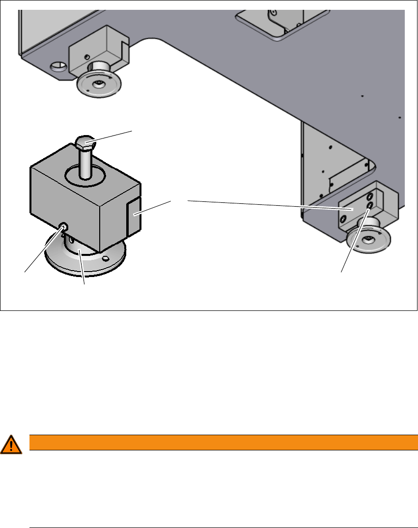
4.3.6 Setting the machine height 900 mm to 930 mm
The machine stands on 4 feet.
4
Fig. 4.3 - 2 Adjusting the height from 900 mm up to 930 mm
(1) Setting screw for adjusting the height
(2) Locking screw
(3) Machine feet
(4) Clamping
(5) Three clamping screws
4
WARNING
Risk of injuries!
After loosening the clamps, the machine feet could still fall out, despite being secured with
the grub screw in the groove, and could then injure hands and feet.
Hold the machine feet while fastening, to prevent it falling down.
Take care that your hands and feet can not be hit.
(3)
(1)
(2)
(4)
(5)