00198051-01_IM_SetupCenter_8.0_EN.pdf - 第82页
Barcode-Scanner Installation Motorola Scanner 6.3.5 Motorola / Symbol Scanner Configuration 82 Installation Manual SIPLACE Setup Center 8.0 Setting 1D or 2D barcodes for Mobile Scanners ► Select the Barcode tab ► Choose …
Barcode-Scanner Installation
6.3.5 Motorola / Symbol Scanner Configuration Motorola Scanner
Installation Manual SIPLACE Setup Center 8.0 81
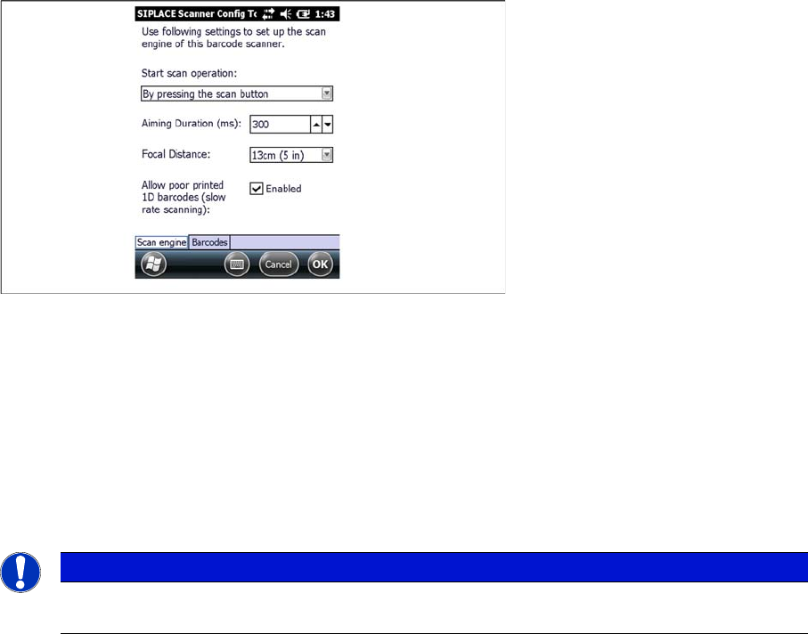
SIPLACE Scanner Config Tool
You can change the following scan parameters here:
▪ Start scan operation:
– By pressing the scan button
– By releasing the scan button (recommended)
▪ Aiming Duration (ms):
Sets the time, how long a user is able to target a barcode with target laser.
▪ Focus Position:
– Far: You have to focus a barcode in scan range of about 23 cm (9 inches).
– Near: You have to focus a barcode in scan range of about 13 cm (5 inches).
▪ Allow poor printed 1D barcodes (slow rate scanning):
Use this setting, if most of your barcodes cannot be read in case of light damage.
► Press Ok or Apply to save the settings.
NOTICE
This setting is depending on barcode size. If you have problems to read your 1D barcodes with
small size, change the setting to “Near”.
Barcode-Scanner Installation
Motorola Scanner 6.3.5 Motorola / Symbol Scanner Configuration
82 Installation Manual SIPLACE Setup Center 8.0
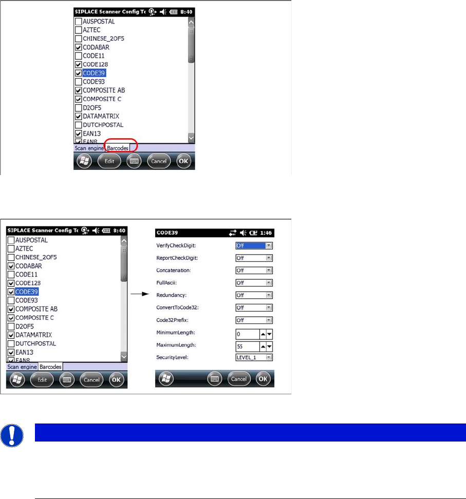
Setting 1D or 2D barcodes for Mobile Scanners
► Select the Barcode tab
► Choose the allowed 1D or 2D barcodes for your mobile scanner here.
► Select the barcode and press Edit to open the additional barcode settings.
► Press Ok to save the settings.
NOTICE
Context menu
Click and hold on a barcode to open the context menu:
All Off: Select none of the barcodes in the list
All On: Select all the barcodes in the list
Docking Station Installation
7.2.1 CAN Bus Address of the Docking Station Safety Instructions
Installation Manual SIPLACE Setup Center 8.0 83
7
7 Docking Station Installation
Docking Station Installation
To obtain more details about using the docking station for E-, X- or SX tables, please refer to the current
version of the operating manual.
7.1
7.1 Safety Instructions
Safety Instructions
7.2
7.2 Connections on the Docking Station
Connections on the Docking Station
7.2.1
7.2.1 CAN Bus Address of the Docking Station
CAN Bus Address of the Docking Station
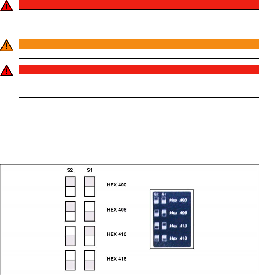
You need to set a CAN Bus address for each docking station. This CAN Bus address must be different
for each docking station.
► Set the CAN Bus address for the docking station.
Docking station: CAN bus addresses
► Make sure that you only assign each address once, when setting the CAN Bus address.
DANGER
Make sure that nobody is using the connected change over table, when you switch the power
on.
The device must not be opened or tampered with.
WARNING
Do not connect the device during placement or when installed inside the placement machine.
DANGER
Never cover the air discharge opening in the integrated fan and the ventilation slits on the side
of the device!
Covering these could lead to overheating and destruction of the power pack.