00198051-01_IM_SetupCenter_8.0_EN.pdf - 第96页
Docking Station Installation Data Connection with CIN-Box 7.4.3 Establishing a Data Connection 96 Installation Manual SIPLACE Setup Center 8.0 Step 4 ► A restart of the PC is required. ► Select Reboot now and click Finis…
Docking Station Installation
7.4.2 Installing the CIN-Box driver Data Connection with CIN-Box
Installation Manual SIPLACE Setup Center 8.0 95
7.4.2
7.4.2 Installing the CIN-Box driver
Installing the CIN-Box driver
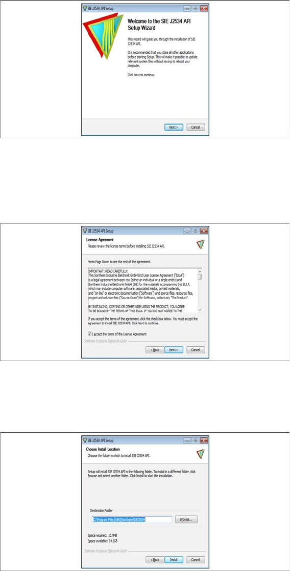
► Open the folder \3rdparty installer\Sontheim\CIN\2.8.4.48 and select the application Setup.exe on
the Setup Center installation CD.
Step 1
► Click Next.
Step 2
► Read the license agreement relating to use of this software and select I accept the terms in the Li
-
cense Agreement to accept the license agreement.
► Click Next.
Step 3
► Choose the install location.
► Click Install.
Docking Station Installation
Data Connection with CIN-Box 7.4.3 Establishing a Data Connection
96 Installation Manual SIPLACE Setup Center 8.0
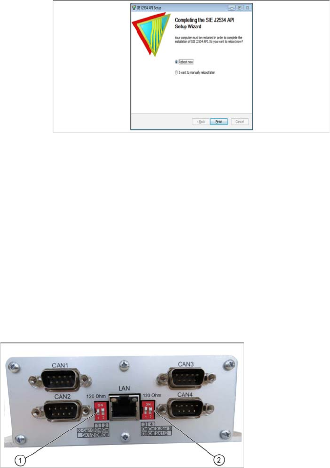
Step 4
► A restart of the PC is required.
► Select Reboot now and click Finish.
7.4.3
7.4.3 Establishing a Data Connection
Establishing a Data Connection
Establish a data connection between the docking station, the CIN-Box and the Setup Center PC. Tow
LAN connections must be available on the Setup Center PC.
The data connection between the CIN-Box and the docking stations is realized via CAN Bus.
Connect the LAN Cable to the PC. Connect the CIN-Box with the CAN cable to the docking station. The
CAN cable has 5 connections, one of which you can use for the CIN-Box connection. This leaves 4 other
connections, allowing you to connect up to 4 docking stations with this cable on one CAN Bus connection
of the CIN-Box. So, you can connect up to 16 docking stations on one CIN-Box.
► Connect the LAN cable from the Setup Center PC to the CIN-Box LAN connection.
► Connect the CAN cable to the CAN connection at your docking station. This can be found on the
back of the docking station.
► Connect the CAN cable to the CIN-Box (CAN Bus 1, 2, 3 or 4).
► See the connection scenarios below for CAN Bus cable connection.
CIN-Box
1. CAN Bus Address Switch (CAN1/2)
2. CAN Bus Address Switch (CAN3/4)
Docking Station Installation
7.4.4 Connection Examples with CIN-Box Data Connection with CIN-Box
Installation Manual SIPLACE Setup Center 8.0 97
7.4.4
7.4.4 Connection Examples with CIN-Box
Connection Examples with CIN-Box
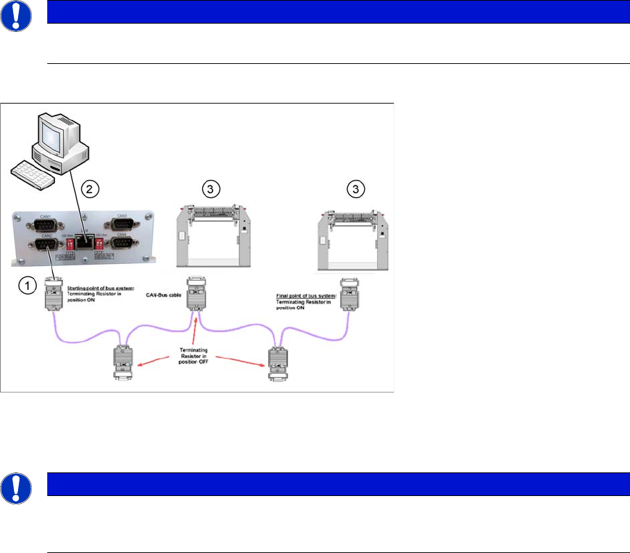
Connection Example 1 (One CIN-Box)
1. CAN Bus cable connection to CIN-BOX
2. Setup Center PC to CIN-Box LAN connection
3. Docking Station X or SX
NOTICE
The first and the last terminating resistor must always be switched ON and the other switched
OFF independent of the number of docking stations.
NOTICE
The integrated terminal resistor can be connected and simultaneously connects / disconnects
the outgoing bus cable when deactivating / activating. This allows an easy start up of the bus
system one segment at a time.