00198051-01_IM_SetupCenter_8.0_EN.pdf - 第84页
Docking Station Installation Connections on the Docking Station 7.2.2 Data Connection of the Docking Station 84 Installation Manual SIPLACE Setup Center 8.0 7.2.2 7 . 2 . 2 D a t a C o n n e c t io n o f t h e D o c k in…
Docking Station Installation
7.2.1 CAN Bus Address of the Docking Station Safety Instructions
Installation Manual SIPLACE Setup Center 8.0 83
7
7 Docking Station Installation
Docking Station Installation
To obtain more details about using the docking station for E-, X- or SX tables, please refer to the current
version of the operating manual.
7.1
7.1 Safety Instructions
Safety Instructions
7.2
7.2 Connections on the Docking Station
Connections on the Docking Station
7.2.1
7.2.1 CAN Bus Address of the Docking Station
CAN Bus Address of the Docking Station
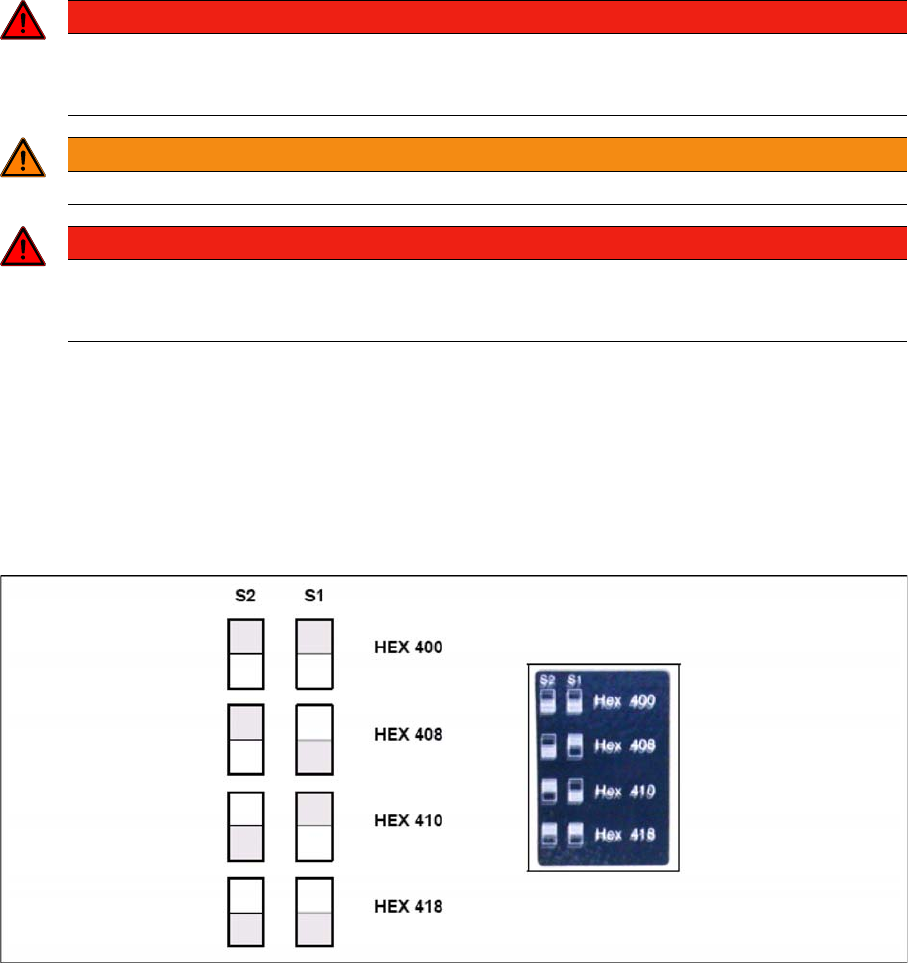
You need to set a CAN Bus address for each docking station. This CAN Bus address must be different
for each docking station.
► Set the CAN Bus address for the docking station.
Docking station: CAN bus addresses
► Make sure that you only assign each address once, when setting the CAN Bus address.
DANGER
Make sure that nobody is using the connected change over table, when you switch the power
on.
The device must not be opened or tampered with.
WARNING
Do not connect the device during placement or when installed inside the placement machine.
DANGER
Never cover the air discharge opening in the integrated fan and the ventilation slits on the side
of the device!
Covering these could lead to overheating and destruction of the power pack.
Docking Station Installation
Connections on the Docking Station 7.2.2 Data Connection of the Docking Station
84 Installation Manual SIPLACE Setup Center 8.0
7.2.2
7.2.2 Data Connection of the Docking Station
Data Connection of the Docking Station
Establish a data connection between the docking station and the Setup Center PC. This data connection
is realized via a CAN Bus. Ensure that you have already installed the CAN card in your PC.
Connect the CAN cable to the docking station and the PC. This CAN cable has 5 connections, one of
which you can use for the PC. This leaves 4 other connections, allowing you to connect up to 4 docking
stations with this cable.
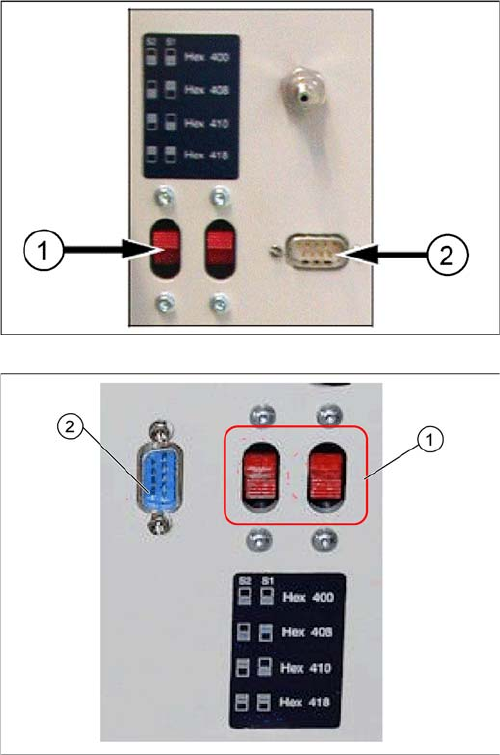
► Connect the CAN cable to the CAN connection at your docking station. This can be found on the
back of the docking station.
► Connect the CAN cable to the CAN card on the PC (CAN Bus 1 or 2).
See the connection scenarios below for CAN Bus cable connection.
Docking Station X
1. CAN Bus Address Switch
2. CAN Connection
Docking Station SX
1. CAN Bus Address Switch
2. CAN Connection
Docking Station Installation
7.2.3 Compressed Air and Power Supplies Connections on the Docking Station
Installation Manual SIPLACE Setup Center 8.0 85
7.2.3
7.2.3 Compressed Air and Power Supplies
Compressed Air and Power Supplies
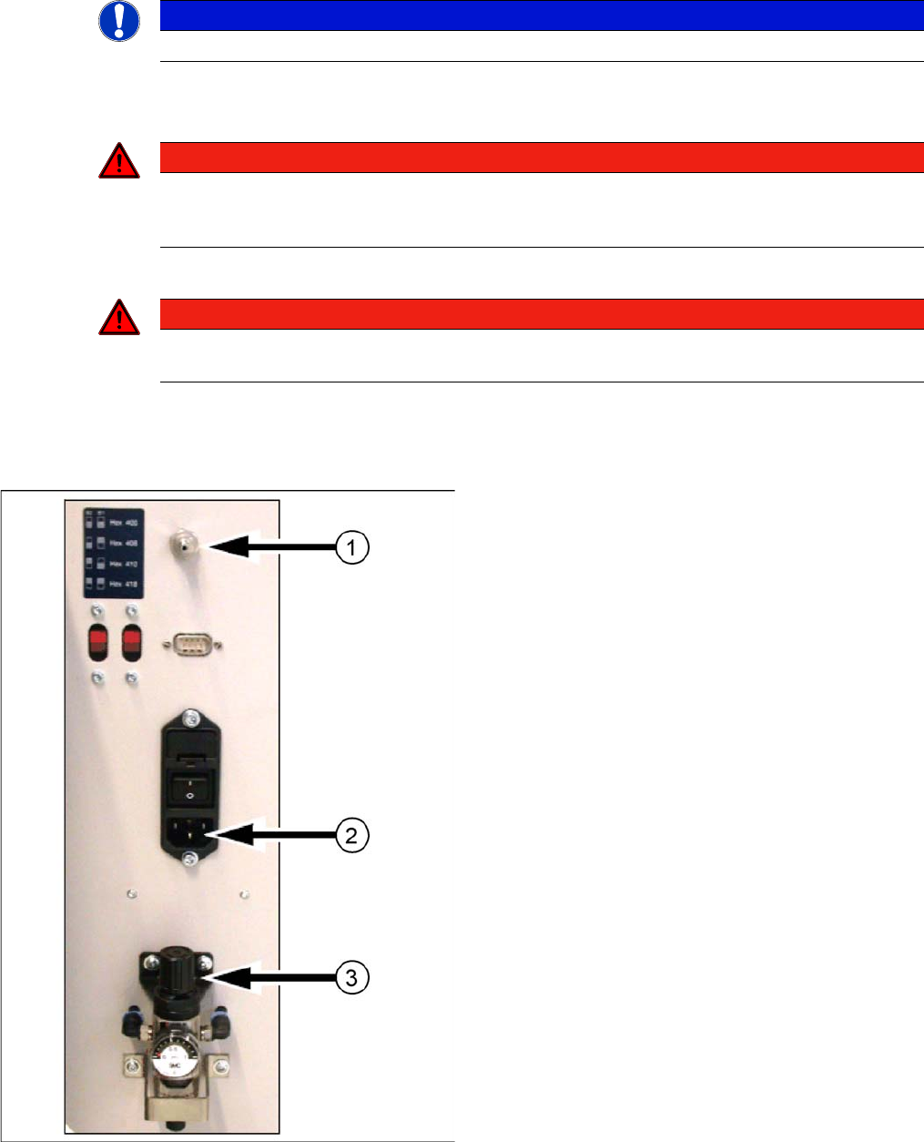
► Connect to the compressed air supply.
► Set the pressure reducer on the pneumatic connection (external) to 5.5 bar.
► Switch off the power supply and connect the CAN Bus cable to the device.
► Switch on the power supply.
► You will find a control lamp on the front of the device. This will shine when power is correctly supplied
to the device.
NOTICE
The compressed air and power connections can be found on the back of the docking station.
DANGER
Never cover the air discharge opening in the integrated fan and the ventilation slits on the side
of the device!
Covering these could lead to overheating and destruction of the power pack.
DANGER
Make sure that nobody is using the connected change over table when you switch the power
on.
Docking station: compressed air and power supplies
Docking Station X
1. Compressed Air Connection
2. Power Connection
3. Set Compressed Air