ThermoFlex-Manual.pdf - 第116页
ThermoFlex B-1 Thermo Scientific Appendix B V oltage Configuration Instructions Ther moFlex 900 and 1400 chillers equipped with the 115V 60Hz, 100v 50/60Hz V ariable V oltag e option and Ther moFlex 900 to 5000 chillers eq…

ThermoFlex A-1
Thermo Scientific
Appendix A Country Specific
230 VAC, 50 Hz, 1Ø Requirements
Refer to the nameplate label located on the rear of the chiller for specic
electrical requirements.
1. Chillers shipped to the following locations require a 16 Amp service:
Afghanistan, Albania, Algeria, Andorra, Angola, Argentina, Armenia,
Austria, Azerbaijan, Belarus, Belgium, Benin, Bolivia, Bosnia and
Herzegovina, Brazil, Bulgaria, Burkina Faso, Burundi, Cambodia,
Cameroon, Cape Verde, Central African Republic, Chad, Chile, Comoros,
Congo, Croatia, Czech Republic, Denmark, Djibouti, DR Congo,
Ecuador, Egypt, Eritrea, Estonia, Ethiopia, Finland, France, French
Guiana, Gabon, Georgia, Germany, Greece, Guinea, Hungary, Iceland,
Indonesia, Iran, Iraq, Israel, Italy, Ivory Coast, Jordan, Kazakhstan,
Kyrgyzstan, Latvia, Lebanon, Liberia, Libya, Liechtenstein, Lithuania,
Luxembourg, Madagascar, Mali, Mauritania, Moldova, Monaco,
Mongolia, Morocco, Mozambique, Namibia, Nepal, Netherlands, Niger,
North Korea, Norway, Paraguay, Peru, Poland, Portugal, Romania,
Russia, Rwanda, Saint Vincent and the Grenadines, San Marino, Sao
Tome and Principe, Saudi Arabia, Senegal, Serbia, Slovakia, Slovenia,
Somalia, South Africa, South Korea, Spain, Sweden, Switzerland, Syria,
Tajikistan, Thailand, Togo, Tunisia, Turkey, Turkmenistan, Ukraine,
Uruguay, Uzbekistan, Vanuatu, Vatican City, Vietnam.
2. Chillers shipped to the following locations require a 15 Amp service:
Australia, China, Fiji Islands, Nauru, New Zealand, Papua New Guinea,
Solomon Island, Tonga, Tuvalu.
3. Chillers shipped to the following locations require a 13 Amp service:
Abu Dhabi, Bahrain, Bangladesh, Botswana, Brunei, Cyprus, Dominica,
Gambia, Ghana, Gibraltar, Grenada, Hong Kong, India, Ireland, Kenya,
Kiribati, Kuwait, Lesotho, Malawi, Malaysia, Maldives, Malta, Mauritius,
Myanmar, Nigeria, Oman, Pakistan, Qatar, Saint Lucia, Seychelles, Sierra
Leone, Singapore, Sri Lanka, Sudan, Swaziland, Tanzania, Uganda,
United Arab Emirates, United Kingdom Yemen, Zambia, Zimbabwe.
ThermoFlex B-1
Thermo Scientific
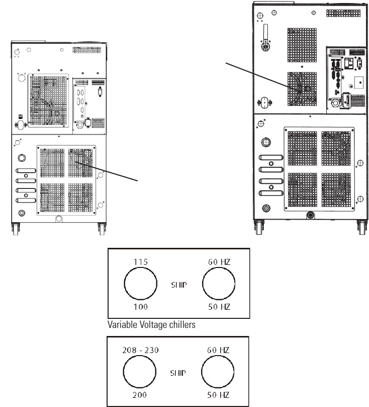
Appendix B Voltage Configuration Instructions
ThermoFlex 900 and 1400 chillers equipped with the 115V 60Hz, 100v 50/60Hz Variable Voltage option and
ThermoFlex 900 to 5000 chillers equipped with 200-230V 50/60Hz Global Voltage option have a voltage
conguration panel located on the rear of the chiller behind an access panel, see Figure B-1.
• Use a 1/4” socket to remove the four screws securing the access panel to the chiller.
• The conguration panel has two 3-position toggle switches, one for voltage and one for frequency. All chillers
are shipped with the toggle switch in the center SHIP position. Place each switch to the settings that match
the voltage/frequency supplied to the chiller.
Note For ThermoFlex900-2500 global voltage chillers, the compressor and fan will not operate when the
switch is in the SHIP position.
• Reinstall the access panel.
Access Panel for
900 - 2500 chillers.
Access Panel for
3500 - 5000
chillers.
Variable Voltage chillers
Global Voltage chillers
Figure B-1 Variable/Global Voltage Chillers
ThermoFlex C-1
Thermo Scientific
Appendix C Analog I/0 and Remote Sensor
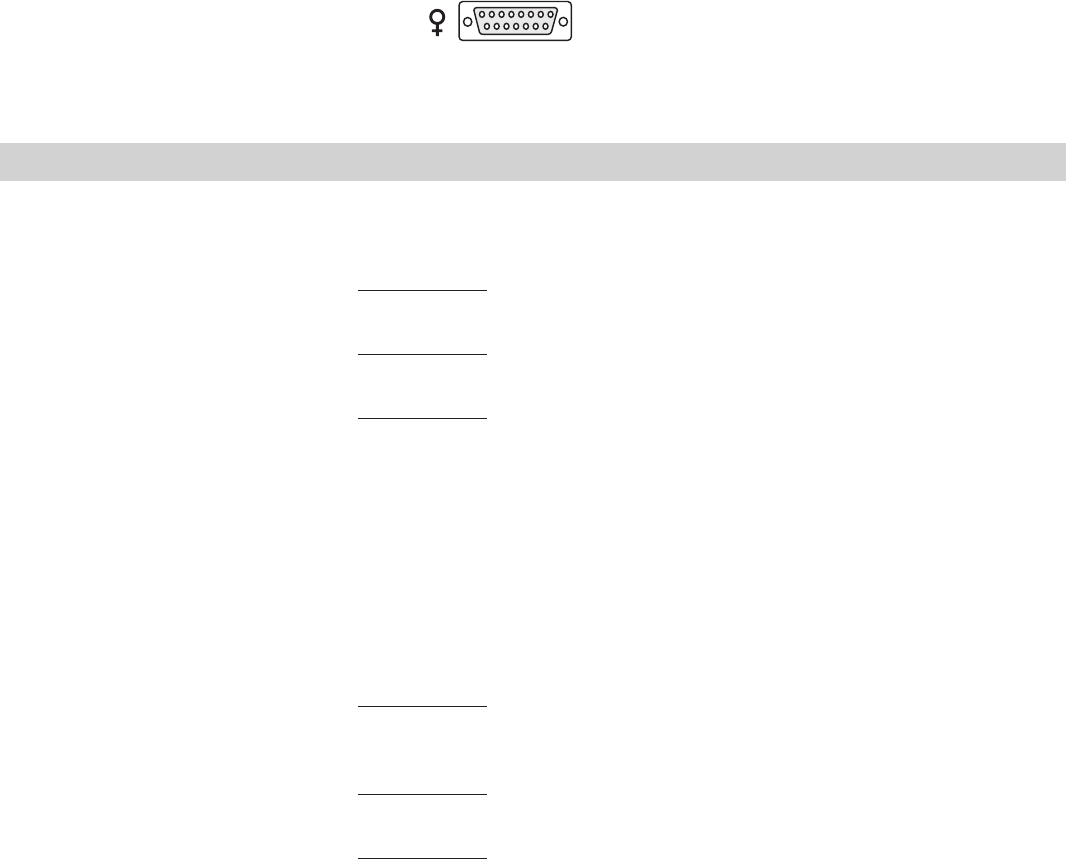
Analog I/O Connector Pinout
Install your analog input/output device to the 15-pin female connector on the rear of the chiller. Analog I/O is
activated using the Setup Loop, see page C-3.
PIN NAME NOTES DEFINITION
1 DIGITAL GROUND Common round connection for pins 12, 13 and 14
2 Not Used
3 LOW LEVEL Note 1 Dry Relay Contact: Reference to pin 11.
(Only if option chosen) Closes if either level switch is in the “low” position for more than 1 second.
4 CONFIGURABLE RELAY 2 Note 1 Dry Relay Contact: Reference to pin 11.
Closes when any configured fault or warning occurs, see Table 2.
5 PUMP ON Note 1 Dry Relay Contact: Reference to pin 11.
Closes when pump is turned on.
Opens when pump is turned off.
6 ANALOG GROUND Common for analog signals (pins 2, 7 and 15)
7 RESERVOIR TEMP OUT Note 2 Analog Voltage Output 0-10VDC, 10mV/°C, or 4-20mA: Reference to pin 6.
OR EXTERNAL SENSOR This voltage output is proportional to the reservoir fluid temperature:
TEMPERATURE IF Default scale= 0–10V (where: 0V = Low Temp Span, 10V = Hi Temp Span)
EXTERNAL SENSOR Optional Range = 10mV/
O
C. (Ex: 200mV = 20°C) (Max Load @ 10V = 5mA)
ENABLED or 4-20mA, 4mA = low temp span, 20 mA = high temp span (maximum output
current = 5mA @10VDC.
8 LOW FLOW Note 1 Dry Relay Contact: Reference to pin 11.
(Only if option chosen) Closes when a low flow occurs while the pump is on. Note: To allow the pump to get up to
speed at startup, the pump runs for 3 - 5 seconds before the low flow sensor is read.
9 CONFIGURABLE RELAY 1 Note 1 Dry Relay Contact: Reference to pin 11.
(Normally Open) Closes when any of the configured faults occur, see Table 1.
10 CONFIGURABLE RELAY 1 Note 1 Dry Relay Contact: Reference to pin 11.
(Normally Closed) Complement of pin 9 (open when pin 9 is closed).
11 RELAY COMMON Common for all relay contacts (pins 3, 4, 5, 8, 9, 10).
12 REMOTE START Note 3 Connect to pin 1 to allow chiller to be remotely turned on/off through pin 14
ENABLE REMOTE START.
Note 1: All relay contacts (except for Pin 10) are normally OPEN when power is off. Pin 10 contacts are normally CLOSED when power is off. Relay
contacts are rated: 24V AC/DC, 2A, <= 0.08 Ohm maximum each or 5A total for all relays combined, 1mA minimum, switching capacity: 48VA/48W
(Resistive load only).
Note 2: Default = 0-10VDC
Note 3: Connect to digital ground (pin 1) using a low resistance connection (gold contact relay).
8 7 6 5 4 3 2 1
15 14 13 12 11 10 9