ThermoFlex-Manual.pdf - 第40页
Section 3 3-2 ThermoFlex Thermo Scientific drain back into the c hiller and cause spillag e. Ther mo Fisher offers an anti-drainback kit to pre…
ThermoFlex 3-1
Thermo Scientific
Section 3 Installation
Ambient Temperature Range* 10°C to 40°C (50°F to 104°F)
Relative Humidity Range 10% to 80% (non-condensing)
Operating Altitude* Sea Level to 8000 feet (2438 meters)
Overvoltage Category II
Pollution Degree 2
Degree of Protection IP 20
Never place the chiller in a location where excessive heat, moisture,
inadequate ventilation, or corrosive materials are present.
Note Refer to the nameplate information on the rear of the chiller.
Air-cooled chillers retain their full rated capacity at 20°C setpoint in ambient
temperatures up to 25°C (77°F). For ambient temperatures above 25°C please
de-rate the cooling capacity 3% for every 1°C above 25°C (77°F), up to a
maximum ambient temperature of 40°C (104°F). Note that when operating
at a process temperature lower than 20°C the de-rate percentage may increase
due to additional gains from losses to ambient.
Note Depending on the setpoint and ambient temperatures, there may be a
heat gain or loss through the plumbing resulting in a variation from setpoint
temperature at the application inlet. Applications with large temperature
variations between ambient and setpoint temperatures, and/or long plumbing
lengths, may require additional insulation.
ThermoFlex2500 air-cooled chillers have a two-speed fan. Should the chiller's
internal ambient temperature reach 50°C for 30 seconds, or reach 53°C, the
fan speed will switch from slow speed to high speed to maintain internal
temperatures within acceptable limits. When the temperature reaches 44°C or
below for at least 15 minutes the speed will return to low. When in high speed
Note High speed is required for the chiller to achieve its 2500 watt cooling
capacity. At high-end operating conditions the fan can be set to run at high
speed all the time using the controller's Setup Loop, see Section 4.
Site Requirements
*Because of the decrease in air density, maximum temperature for the air entering an air-cooled
ThermoFlex is reduced by 1°C per 1,000 feet above sea level. In addition, cooling capacity is
reduced 1.2% per 1,000 feet above sea level.
CAUTION
Section 3
3-2 ThermoFlex
Thermo Scientific
drain back into the chiller and cause spillage. Thermo Fisher offers an
anti-drainback kit to prevent any spillage, see Section 5.
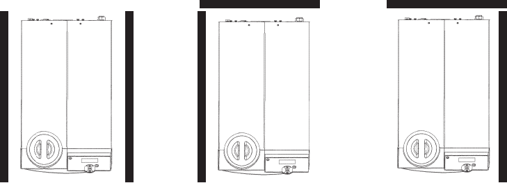
Air-cooled chillers can be installed with both sides blocked, or one side and
the rear. See Figure 3-1. The front of the chiller needs a minimum clearance
of 24". Air will enter the front of the system and exit through the sides and
rear.
Having two sides blocked can impact the chiller's performance due to
ensure that the following requirements are met:
Process Setpoint Temperature: Below 30°C (86°F)
Ambient: Below 40°C (104°F)
Before operating the chiller in conditions outside any of those listed on this
Support to review your installation.
Figure 3-1 Minimum Clearance
Section 3
ThermoFlex 3-3
Thermo Scientific
Electrical
Requirements
The chiller's construction provides protection against the risk of
electrical shock by grounding appropriate metal parts. The protection
will not function unless the power cord is connected to a properly
grounded outlet. It is the user's responsibility to assure a proper
ground connection is provided.
The chiller must be installed in accordance with the National Electrical Code
and the with reference to the information on the chiller's nameplate located
on the rear.
Locate the chiller so it is near, and has easy access to, its disconnecting device.
The user is responsible to ensure that the line cord provided meets local
The chiller is intended for use on a dedicated outlet. The ThermoFlex has
an internal circuit protection that is equivalent (approximately) to the branch
circuit rating. This is to protect the ThermoFlex, and is not intended as a
substitute for branch circuit protection.
DANGER
* Refer to Appendix A for country specific ratings. Continued on next page.
Electrical Service Requirements (Standard chillers):
ThermoFlex900 Voltage ±10% Frequency Phase Branch Circuit
Requirements
Line Cord
Plug
100 VAC 50 Hz 1Ø 15A 5-15P
115 VAC 60 Hz 1Ø 15A 5-15P
200 VAC 50 Hz 1Ø 15A 6-15P
208-230 VAC 60 Hz 1Ø 15A 6-15P
230 VAC 50 Hz 1Ø *16A
1
, 15A
2
, 13A
3
-
ThermoFlex1400 Voltage ±10% Frequency Phase Branch Circuit
Requirements
Line Cord
Plug
100 VAC 50 Hz 1Ø 20A 5-20P
115 VAC 60 Hz 1Ø 20A 5-20P
200 VAC 50 Hz 1Ø 15A 6-15P
208-230 VAC 60 Hz 1Ø 15A 6-15P
230 VAC 50 Hz 1Ø *16A
1
, 15A
2
, 13A
3
-
ThermoFlex2500 Voltage ±10% Frequency Phase Branch Circuit
Requirements
Line Cord
Plug
200 VAC P 1, P 2 Pump 50 Hz 1Ø 15A 6-15P
208-230 VAC P 1, P 2 Pump 60 Hz 1Ø 15A 6-15P
200 VAC T 1 Pump 50 Hz 1Ø 20A 6-20P
208-230 VAC T 1 Pump 60 Hz 1Ø 20A 6-20P
230 VAC 50 Hz 1Ø *16A
1
, 15A
2
, 13A
3
-