ThermoFlex-Manual.pdf - 第8页
• Press • The display will f ash between Hi t and 42 • If desi red, use to adjust the value • Press to sequence to the next display • Press • The display will f ash between Lo t and 3 • If desi red, use to adjust the val…
MIN
LEVEL
MAX
LEVEL
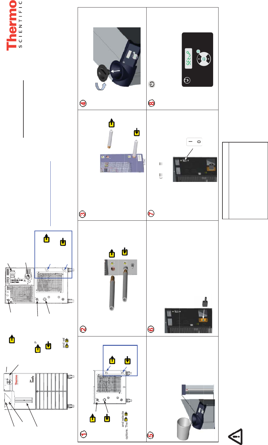
Slowly fill reservoir with clean process fluid (see Table 1),
utilizing sight tube for easy fluid level monitoring. When the reser-
voir is full replace the reservoir cap, hand tight. Since the reservoir
capacity may be small compared to your application and air may
need to be purged from the lines, have extra cooling fluid on hand
to keep the system topped off when external circulation is started.
Press .
The controller will display SEtuP.
Note: If the unit is equipped with a deionization filter cartridge
refer to the manual, Section 5, for installation.
Please see reverse side for additional steps.
Pull out the plastic shipping plugs.
Remove the reservoir cap by unscrewing it counter-
clockwise.
Verify the appropriate voltage. For units supplied with a line cord,
insert female end of power cord into chiller and then insert male end
of power cord into power outlet. (The line cord is located under the
shipping crate’s lid. Do not discard the lid
until the cord is located.)
Connect the ThermoFlex FACILITY OUTLET (A) to your facility
water return or drain. Connect the ThermoFlex FACILITY INLET (B)
to your facility water supply. Ensure the connections are sealed and
secure.
What you need to get started:
• An adjustable wrench
• Facility water supply and return (water-cooled units)
• Appropriate hose or plumbing
• Appropriate size clamps or connection type
• Teflon
®
Tape or appropriate sealant
Safety Precautions:
The unit is designed for indoor use only.
Never place unit in a location where excessive heat, moisture, inadequate
ventilation, or corrosive materials are present.
Never connect process fluid lines to your facility water supply or to any
pressurized liquid source.
If your unit is equipped with a positive displacement pump (P1 or P2),
ensure your application plumbing lines and fittings are rated to withstand a
minimum of 185 psi.
Before using any fluid or performing maintenance where contact with the
fluid is likely refer to the manufacturer’s MSDS for handling precautions.
For water-cooled units only.
See Figure A.
See Figure B.
See Figure B. See Figure B.
See Figure B.
See Figure B.
See Figure A.
See Figure A.
Connect the ThermoFlex PROCESS OUTLET (A) to the fluid inlet
on your application. Connect the ThermoFlex PROCESS INLET (B) to
the fluid outlet on your application. Ensure the connections are sealed
and secure. For air-cooled units skip to Step 4.
For ThermoFlex900 through 10000 units, place the circuit
protector to the on ( I ) position. The controller display will indicate
a series of scrolling bars (
). The bars will scroll upward
indicating the unit is initializing, this takes approximately 15 sec-
onds. For other units the bars appear when power is supplied to
the unit.
B
A
B
A
PROCESS
INLET
PROCESS
OUTLET
FACILITY
INLET
FACILITY
OUTLET
Note: Be careful not
to fill the reservoir
above MAX LEVEL fill
line. This will result in
a unit over flow error
(O FLO) which will
cause the unit to shut
down.
Thermo Scientific Part Number U00945
Rev. 11/19/2012
Note: ThermoFlex900-5000 units equipped
with the V
ariable Voltage or Global Voltage
option have a voltage configuration panel
located behind an access panel on the rear
of the unit. Refer to the V
oltage Instruction
Sheet shipped with the unit, or see manual
Appendix B.
Note: For units requiring hard wiring see
Section 3 in the manual.
Water-cooled units only
FACILITY
INLET
FACILITY
OUTLET
PROCESS
INLET
PROCESS
OUTLET
Use of any fluid not listed below will void the
manufacturer’s warranty.
Filtered/Single Distilled Water
Deionized water (1-3 MΩ-cm, compensated)
0 – 75% Ethylene Glycol/Water
0 – 75% Propylene Glycol/Water
Table 1 - Acceptable Fluids:
Facility Water Connections (FNPT)
ThermoFlex1400 - 5000 Inlet/Outlet ½” cast bronze
ThermoFlex7500 - 10000 Inlet/Outlet ¾” cast bronze
ThermoFlex15000 - 24000 Inlet ¾” cast bronze
ThermoFlex15000 - 24000 Outlet ¾” stainless steel
Controller
See Step 8.
Power Button
See Step 8.
Integrated Funnel
See Step 5.
Level Indicator
See Step 5.
Figure A
Reservoir Cap
See Step 4.
Process Outlet -
See Steps 1 and 2.
Process Outlet -
(ThermoFlex900-
5000 units with PD
pumps and flow
transducers)
Circuit Protector
See Step 7.
Power Inlet for units
not hard-wired
See Step 6.
Process Inlet -
See Steps 1 and 2.
Facility Inlet
See Steps 1 and 3.
Facility Outlet
See Steps 1 and 3.
Water-cooled units only
Figure B
Figure B is typical.
Locations vary with unit size
and selected options. The
labels identify the
exact location.
Locations vary with
unit size and selected
options. The
labels identify the exact
location.
Process Fluid Connections (FNPT)
Outlet
ThermoFlex900 - 10000 P 1 P 2 T0 T 1 1/2" cast bronze
ThermoFlex3500 - 5000 P 3 P 4 3/4" cast bronze
ThermoFlex7500 - 24000 P 3 P 5 T 5 1" wrought copper
Inlet - Same size as outlet all units stainless steel
Supplied Adapters
P 1 P 2 T0 T 1 1/2" x 3/8'' Polyethylene and 1/2" x 1/2" Nylon
P 3 P 4 3/4 MPT x 1/2 barb PVC
P 3 P 5 T 5 1" MPT x 1" Barb PVC and 1" MPT x 3/4" Barb PVC
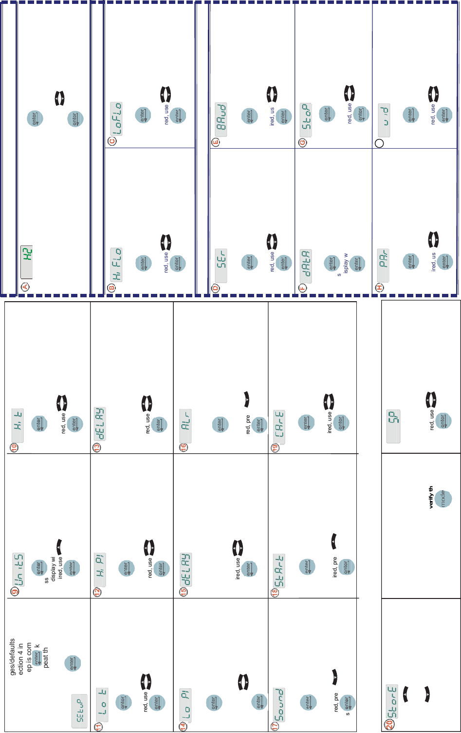
• Press
• The display will f ash between Hi t and 42
• If desired, use
to adjust the value
• Press
to sequence to the next display
• Press
• The display will f ash between Lo t and 3
• If desired, use
to adjust the value
• Press
Lo t sets the fl uid’s Low
Temperature Alarm Limit.
Range: +3°C to +42°C
Factory Default: 3°C
• Press
• The display will f ash between Hi P1 and the default
• If desired, use
to adjust the value
• Press
Hi P1 sets the Pump’s High
Pressure Discharge Alarm Limit.
Range: Varies by pump
Factory Default: Varies by pump
• The display will f ash between dELAY and 0
• If desired, use
to adjust the value
• Press
dELAY is the length of time the pump
can exceed the Hi P1 Alarm Limit
before shutting down.
Range: Varies by pump
Factory Default: 0 seconds
• Press
• The display will f ash between Lo P1 and the
default
• If desired, use
to adjust the default
• Press
Lo P1 sets the Pump’s Low
Pressure Discharge Alarm
Limit.
Range: Varies by pump
Factory Default: Varies by pump
dELAY is the length of time the
pump can exceed the Lo P1
Alarm Limit before shutting down.
Range: 0 to 30 seconds
Factory Default: 10 seconds
• The display will f ash between dELAY and 10
• If desired, use
to adjust the value
• Press
• Press
• The display will f ash between ALr and fLt
• If desired, press
to display indC
• Press
Turns the unit’s audible alarm
on or off.
Range: on or OFF
Factory Default: on
• Press
• The display will f ash between Sound and on
• If desired, press
to display OFF
• Press
• Press
• The display will f ash between StArt and OFF
• If desired, press
to display on
• Press
StArt enables/disables auto
restart.
Range: on or OFF
Factory Default: OFF
• Press
• The display will f ash between CArE and L1
• If desired, use
to change display to off, L2 or L3
• Press
CArE is used to set the preventative
care cleaning frequency reminder for
the unit’s air and fl uid fi lters.
Range: off, L1 - 1000 hours,
L2 - 2000 hours, L3 -3000 hours
Factory Default: L1
• Press
to save all settings
The unit will automatically start.
• Press to disregard all changes and
restore the factory default values.
The display will go blank.
The Setup procedure is now complete.
When the unit starts the controller will
display the process fl uid temperature.
If desired, you can change/verify the
unit’s setpoint by pressing
.
SP is used to adjust the setpoint.
Range: +5°C to +40°C
Factory Default: +20°C
• The display will f ash between SP and 20
• If desired, use
to change the setting
• Press
to save the new setpoint and return to
the temperature display
If applicable, see boxes on right to set up options. For units with Analog I/O (ACOM) refer to the additional
quick start supplied with your unit.
Quick Start - Used for Initial Start Up Only — perform steps 9 to 20 for all units.
** fLt = fault (shut down)
** indC = indicate (continue to run)
Hi t sets the fl uid’s High
Temperature Alarm Limit.
Range: +3°C to +42°C
Factory Default: +42°C
• Press
• The display will f ash between UnitS and °C
• If desired, use
to change the scale to °F
• Press
to sequence to the next display
• Do the same for Flow and Pressure scales
• Press
• The display will f ash between u id and 1
• If desired, use
to change the setting
• Press
HiFLO sets the high fl ow alarm
limit.
Range: Varies by pump
Factory Default: Varies by pump
• Press
• The display will f ash between HiFLO and the default
• If desired, use
to adjust the value
• Press
• Press
• The display will f ash between LoFLO and the default
• If desired, use
to adjust the value
• Press
LoFLO sets the low fl ow alarm
limit.
Range: Varies by pump
Factory Default: Varies by pump
• Press
• The display will f ash between StoP and 1
• If desired, use
to change the setting
• Press
StoP is used to indicate the
number of stop bits.
Range: 2 or 1
Factory Default: 1
u id (unit id) is used in RS485
only. Identifi es devices connected
to the RS485 port.
Range: 1 to 99
Factory Default: 1
• Press
• The display will f ash between SEr and OFF
• If desired, use
to change the mode
• Press
SEr is used to enable/disable
and to confi gure serial
communications mode.
Range: off, rS232, rS485
Factory Default: off
• Press
• The display will f ash between BAud and 9600
• If desired, use
to change the rate
• Press
BAud is used to select the
baud rate (speed) for serial
communication.
Range: 9600, 4800, 2400, 1200,
600, or 300 bits per second.
• Press
• The display will f ash between dAtA and 8
• Press
dAtA is used to display the
number of bits.
Display: 8
• Press
• The display will f ash between PAr and none
• If desired, use
to change the setting
• Press
PAr is used as a means to check
for communication errors.
Range: even, odd, or none
Factory Default: none
Option - Flow Transducer — Steps B and C
If your unit does not have
serial communications see
Step 20.
See Step 20.
Option - Serial Communications (DCOM) — Steps D to I
UnitS are the temperature, fl uid
fl ow (optional) and pressure
scales.
Scales: °C/°F GPM/LPM
PSI/Bar/KPAS
• Press
• The display will f ash between HZ and 60
• If needed, use
to change the frequency
• Press
If your unit does not have a fl ow
transducer or serial communications
see Step 20.
Option - Voltage — Step A
HZ is used to identify the incoming frequency for
units with P 3 - P 5 pumps and variable voltage
capability. The selected frequency automatically
adjusts the fi rmware's fi xed high pressure
default setting.
I
I
Press to continue the
setup procedure.
NOTE: Some ranges/defaults are pump
dependent, see Section 4 in the manual.
Once any Setup step is completed, mean-
ing you pressed the key a second
time, you can not repeat the step to make
corrections. You can make changes after
the unit is started.
NOTE This feature is active only if the unit is
confi gured to shut down, see Step 16
.
NOTE This feature is active only if the unit is
confi gured to shut down, see Step 16
.
ALr confi gures the unit’s reaction
to temperature, pressure, and fl ow
(optional) alarm limits - either shut
down (fLt) or continue to run (indC).
See Section 4 in the manual for more
information.
Range: fLt* or indC**
Factory Default: fLt
MIN
FÜLLSTAND
MAX
FÜLLSTAND
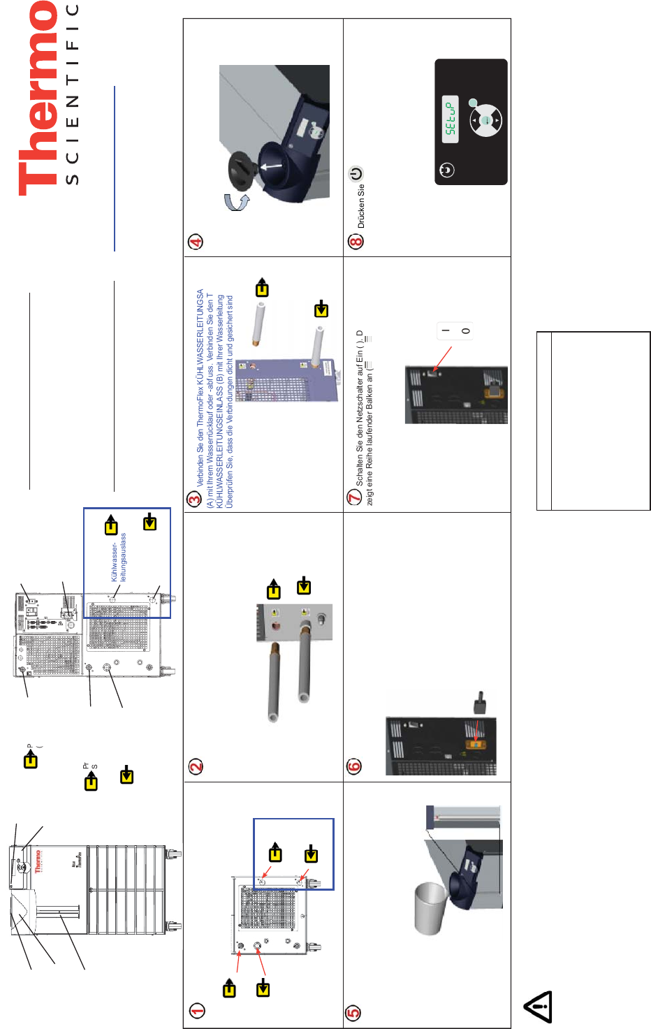
Befüllen Sie den Behälter langsam mit sauberer Prozessf üssigkeit (siehe
Tabelle 1) und kontrollieren Sie den Füllstand über die Füllstandsanzeige. Wenn
der Behälter voll ist, schrauben Sie die Behälterkappe handfest auf. Da mög-
licherweise die Kapazität des Behälters im Vergleich zu Ihrer Applikation eher
gering ist und Luft aus den Leitungen gespült werden muss, halten Sie weitere
Kühl
f üssigkeit zum Nachfüllen bereit, wenn der externe Kreislauf gestartet wird.
Drücken Sie .
Die Steuerung zeigt SEtuP an.
Hinweis: Falls das Gerät mit einer Deionisierungs-
Filterkartusche ausgestattet ist, f nden Sie Hinweise zum
Einsetzen in Abschnitt 5 des Handbuchs.
Weitere Schritte siehe Rückseite.
Ziehen Sie die Kunststoff-Versandstopfen heraus.
Prozessauslass -
Siehe Schritte 1 und 2.
Prozessauslass -
(ThermoFlex900-5000
Geräte mit Verdränger-
pumpen und Durch-
f uss-Messumformern)
Siehe Schritte 1 und 2.
Netzschalter
Siehe Schritt 7.
Stromversorgung für
Geräte mit ortsveränder-
lichem Anschluss.
Siehe Schritt 6.
Prozesseinlass -
Siehe Schritte 1
und 2.
Abbildung B ist eine Beispielabbildung.
Die Anschlussstellen variieren je nach
Gerätegröße und gewählten Optionen.
Schrauben Sie die Behälterkappe entgegen dem Uhr-
zeigersinn ab.
Kontrollieren Sie, dass die korrekte Spannung eingestellt ist.
Stecken Sie bei Geräten mit Stromkabel zunächst das geräteseitige Ende
in das Kühlgerät und anschließend den Stecker in eine Steckdose. (Das
Stromkabel bef ndet sich unter dem Deckel der
Transportkiste. Werfen Sie den Deckel nicht weg,
bevor Sie das Stromkabel gefunden haben.)
Verbinden Sie den ThermoFlex KÜHLWASSERLEITUNGSAUSLASS
(A) mit Ihrem Wasserrücklauf oder -abf uss. Verbinden Sie den ThermoFlex
KÜHLWASSERLEITUNGSEINLASS (B) mit Ihrer Wasserleitung.
Überprüfen Sie, dass die Verbindungen dicht und gesichert sind.
P
(
Kühlwasser-
leitungseinlass
Siehe Schritte 1 und 3.
Kühlwasser-
leitungsauslass
Siehe Schritte 1 und 3.
Nur wassergekühlte
Geräte
Sie benötigen:
• Einen verstellbaren Schraubenschlüssel
• Leitungswasserzu- und -ablauf (wassergekühlte Geräte)
• Passende Schläuche bzw. Leitungen
• Passende Klemmen oder Anschlussstücke
• Tef onband
®
oder geeignete Dichtungen
Nur wassergekühlte Geräte
Sicherheitsvorkehrungen:
Das Gerät darf nur in geschlossenen Räumen betrieben werden.
Stellen Sie das Gerät niemals an Orten auf, wo es übermäßiger Hitze, Feuchtigkeit,
unzureichender Belüftung oder korrosiven Stoffen ausgesetzt ist.
Schließen Sie niemals Prozessf üssigkeitsleitungen an die Kühlwasserversorgung oder an einen
Anschluss für unter Druck stehende Flüssigkeiten an.
Falls Ihr Gerät mit einer Verdrängerpumpe ausgestattet ist, stellen Sie sicher, dass die Leitungen
und Fittings Ihrer Applikation einem Druck von mindestens 185 psi/ca. 9,8 bar standhalten.
Bevor Sie Flüssigkeiten einsetzen oder eine Wartung durchführen, bei denen Sie
möglicherweise mit Flüssigkeiten in Berührung kommen, beachten Sie die im
Sicherheitsdatenblatt des Herstellers beschriebenen Vorsichtsmaßnahmen.
Abbildung B
Nur für wassergekühlte
Geräte
.
Siehe Abbildung A.
Siehe Abbildung B. Siehe Abbildung B. Siehe Abbildung B.
Siehe Abbildung B.
Siehe Abbildung B.
Siehe Abbildung A.
Siehe Abbildung A.
Verbinden Sie den ThermoFlex PROZESSAUSGANG (A) mit dem
Flüssigkeitseingang Ihrer Applikation. Verbinden Sie den ThermoFlex
PROZESSEINGANG (B) mit dem Flüssigkeitsausgang Ihrer Applikation.
Überprüfen Sie, dass die Verbindungen dicht und gesichert sind.
Luftgekühlte Geräte: Weiter mit Schritt 4.
Schalten Sie den Netzschalter auf Ein (I). Die Steuerung
zeigt eine Reihe laufender Balken an (
). Die Balken laufen
aufwärts, um anzuzeigen, dass das Gerät initialisiert wird. Dieser
Vorgang dauert ca. 15 Sekunden.
B
A
B
A
Steuerung
Siehe Schritt 8.
Ein/Aus-Schalter
Siehe Schritt 8.
Integrierter Trichter
Siehe Schritt 5.
Füllstandsanzeige
Siehe Schritt 5.
Abbildung A
Behälterkappe
Siehe Schritt 4.
PROZESS-
EINLASS
PROZESS-
AUSLASS
WASSERLEITUNG
EINLASS
WASSERLEITUNG
AUSLASS
WASSERLEITUNG
EINLASS
WASSERLEITUNG
AUSLASS
PROZESS-
EINLASS
PROZESS-
AUSLASS
Hinweis: Achten Sie
darauf, den Behälter
nicht über die Markierung
MAX LEVEL zu befüllen.
Dies führt zu einem
Überlauf-Fehler (O
FLO) und somit zu einer
Abschaltung des Geräts.
Anschlüsse für Prozessf üssigkeiten (FNPT)
Auslass
ThermoFlex900 - 10000 P1 P2 T0 T1 1/2" Gussbronze
ThermoFlex3500 - 5000 P3 P4 3/4" Gussbronze
ThermoFlex7500 - 24000 P3 P5 T 5
1" geschmiedetes Kupfer
Einlass - Selbe Größe wie Auslass alle Geräte Edelstahl
Kühlwasserleitungsanschlüsse (FNPT)
ThermoFlex1400 - 5000 Einlass/Auslass ½” Gussbronze
ThermoFlex7500 - 10000 Einlass/Auslass ¾” Gussbronze
ThermoFlex15000 - 24000 Einlass ¾” Gussbronze
ThermoFlex15000 - 24000 Auslass ¾” Edelstahl
Hinweis: Bei ThermoFlex900-5000 Geräten
mit der Option Variabler Spannungsbereich
bef ndet sich hinter einer
Abdeckung
auf der Geräterückseite ein Bedienfeld
zur Konf guration der Spannung. Siehe
beigefügte Anweisung zum Einstellen der
Spannung oder Anhang B im Handbuch.
Hinweis: Für Geräte, bei denen ein Festanschluss
erforderlich ist, siehe Abschnitt 3 im Handbuch.
Die Verwendung anderer Flüssigkeiten als der
nachstehend aufgeführten führt zum Verlust der
Herstellergarantie.
Gef ltertes/destilliertes Wasser
Deionisiertes Wasser (1-3 MOhm-cm, kompensiert)
0 – 75 % Ethylenglycol/Wasser
0 – 75 % Propylenglycol/Wasser
Tabelle 1 - Zulässige Flüssigkeiten: