ThermoFlex-Manual.pdf - 第117页
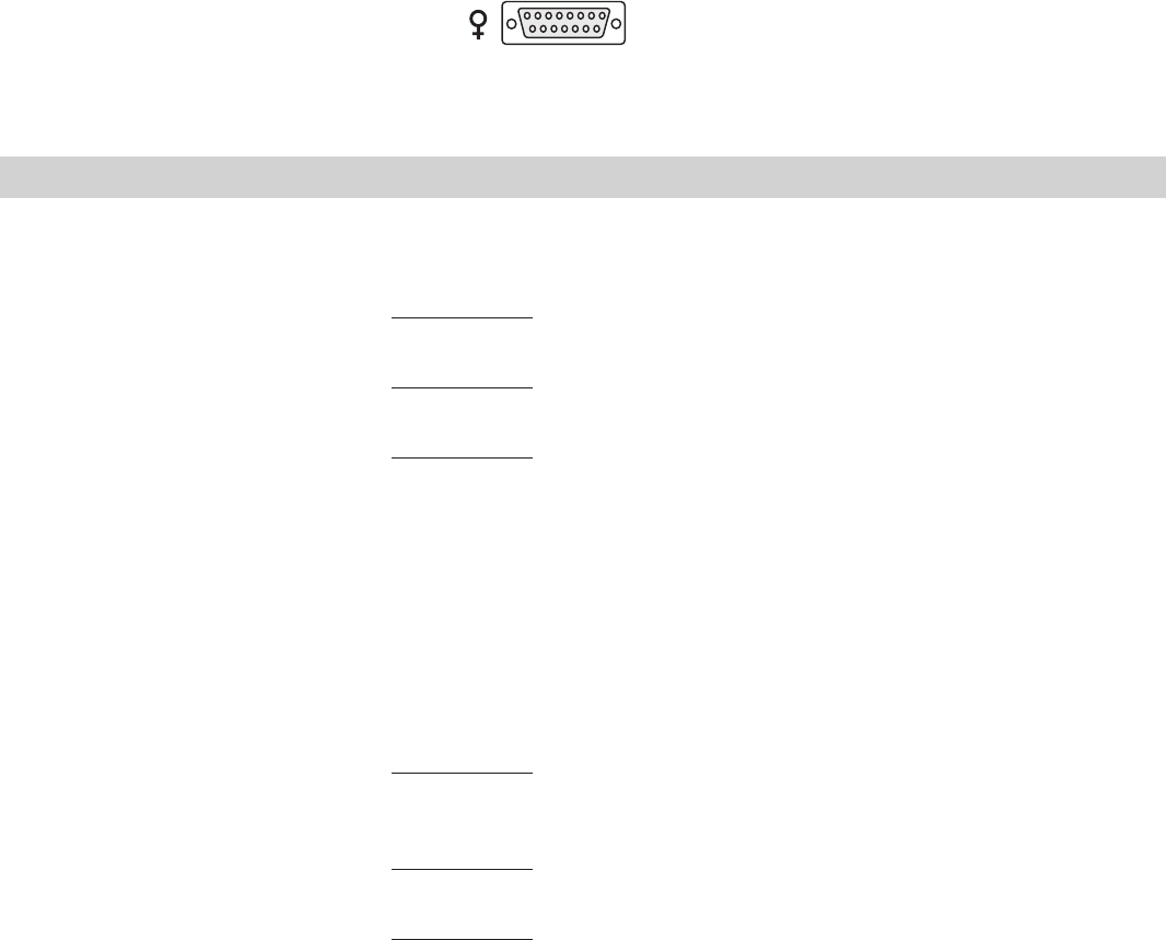
ThermoFlex C-1 Thermo Scientific Appendix C Analog I/0 and Remote Sensor Analog I/O Connector Pinout Install your analog input/output device to the 15-pin female connector on the rear of the chiller . Analog I/O is activ …
ThermoFlex B-1
Thermo Scientific
Appendix B Voltage Configuration Instructions
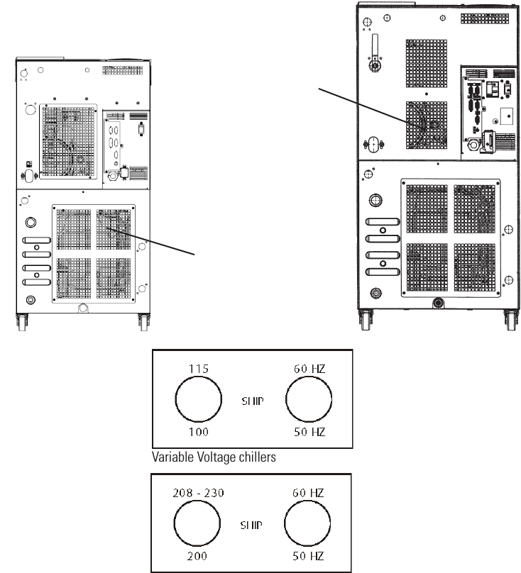
ThermoFlex 900 and 1400 chillers equipped with the 115V 60Hz, 100v 50/60Hz Variable Voltage option and
ThermoFlex 900 to 5000 chillers equipped with 200-230V 50/60Hz Global Voltage option have a voltage
conguration panel located on the rear of the chiller behind an access panel, see Figure B-1.
• Use a 1/4” socket to remove the four screws securing the access panel to the chiller.
• The conguration panel has two 3-position toggle switches, one for voltage and one for frequency. All chillers
are shipped with the toggle switch in the center SHIP position. Place each switch to the settings that match
the voltage/frequency supplied to the chiller.
Note For ThermoFlex900-2500 global voltage chillers, the compressor and fan will not operate when the
switch is in the SHIP position.
• Reinstall the access panel.
Access Panel for
900 - 2500 chillers.
Access Panel for
3500 - 5000
chillers.
Variable Voltage chillers
Global Voltage chillers
Figure B-1 Variable/Global Voltage Chillers
ThermoFlex C-1
Thermo Scientific
Appendix C Analog I/0 and Remote Sensor
Analog I/O Connector Pinout
Install your analog input/output device to the 15-pin female connector on the rear of the chiller. Analog I/O is
activated using the Setup Loop, see page C-3.
PIN NAME NOTES DEFINITION
1 DIGITAL GROUND Common round connection for pins 12, 13 and 14
2 Not Used
3 LOW LEVEL Note 1 Dry Relay Contact: Reference to pin 11.
(Only if option chosen) Closes if either level switch is in the “low” position for more than 1 second.
4 CONFIGURABLE RELAY 2 Note 1 Dry Relay Contact: Reference to pin 11.
Closes when any configured fault or warning occurs, see Table 2.
5 PUMP ON Note 1 Dry Relay Contact: Reference to pin 11.
Closes when pump is turned on.
Opens when pump is turned off.
6 ANALOG GROUND Common for analog signals (pins 2, 7 and 15)
7 RESERVOIR TEMP OUT Note 2 Analog Voltage Output 0-10VDC, 10mV/°C, or 4-20mA: Reference to pin 6.
OR EXTERNAL SENSOR This voltage output is proportional to the reservoir fluid temperature:
TEMPERATURE IF Default scale= 0–10V (where: 0V = Low Temp Span, 10V = Hi Temp Span)
EXTERNAL SENSOR Optional Range = 10mV/
O
C. (Ex: 200mV = 20°C) (Max Load @ 10V = 5mA)
ENABLED or 4-20mA, 4mA = low temp span, 20 mA = high temp span (maximum output
current = 5mA @10VDC.
8 LOW FLOW Note 1 Dry Relay Contact: Reference to pin 11.
(Only if option chosen) Closes when a low flow occurs while the pump is on. Note: To allow the pump to get up to
speed at startup, the pump runs for 3 - 5 seconds before the low flow sensor is read.
9 CONFIGURABLE RELAY 1 Note 1 Dry Relay Contact: Reference to pin 11.
(Normally Open) Closes when any of the configured faults occur, see Table 1.
10 CONFIGURABLE RELAY 1 Note 1 Dry Relay Contact: Reference to pin 11.
(Normally Closed) Complement of pin 9 (open when pin 9 is closed).
11 RELAY COMMON Common for all relay contacts (pins 3, 4, 5, 8, 9, 10).
12 REMOTE START Note 3 Connect to pin 1 to allow chiller to be remotely turned on/off through pin 14
ENABLE REMOTE START.
Note 1: All relay contacts (except for Pin 10) are normally OPEN when power is off. Pin 10 contacts are normally CLOSED when power is off. Relay
contacts are rated: 24V AC/DC, 2A, <= 0.08 Ohm maximum each or 5A total for all relays combined, 1mA minimum, switching capacity: 48VA/48W
(Resistive load only).
Note 2: Default = 0-10VDC
Note 3: Connect to digital ground (pin 1) using a low resistance connection (gold contact relay).
8 7 6 5 4 3 2 1
15 14 13 12 11 10 9
Thermo Scientific
C-2 ThermoFlex
Appendix C
Thermo Scientific
Thermo Scientific
PIN NAME NOTES DEFINITION
13 REMOTE SETPOINT Note 3 Connect to pin 1 to allow the setpoint to be changed remotely through pin 15
ENABLE REMOTE SETPOINT.
14 REMOTE START Note 3 Connect to pin 1 to turn chiller on. Disconnect to turn chiller off.
Note: Pins 1 and 12 must be connected to allow operation from this pin.
15 REMOTE SETPOINT Note 2, 4 Analog Voltage Input 0-10VDC, 10mV/°C, or 4-20mA: Reference to pin 6.
Apply a DC voltage to this pin to adjust the chiller's setpoint:
Default Range = 0 – 10V (where: 0V = Low Temp Span, 10V = Hi Temp Span)
(Input Impedance > 600K)
Optional Range = 10mV/
O
C. (Ex: 200mV = 20°C) (Max Input Voltage = 10VDC,
or 4-20mA, 4mA = low temp span, 20 mA = high temp span.
Note 1: All relay contacts (except for Pin 10) are normally OPEN when power is off. Pin 10 contacts are normally CLOSED when power is off.
Relay contacts are rated: 24V AC/DC, 2A, <= 0.08 Ohm maximum each or 5A total for all relays combined, 1mA minimum, switching capacity:
48VA/48W (Resistive load only).
Note 2: Default = 0-10VDC
Note 3: Connect to digital ground (pin 1) using a low resistance connection (gold contact relay).
Note 4: Remote setpoint must be enabled, pin 13
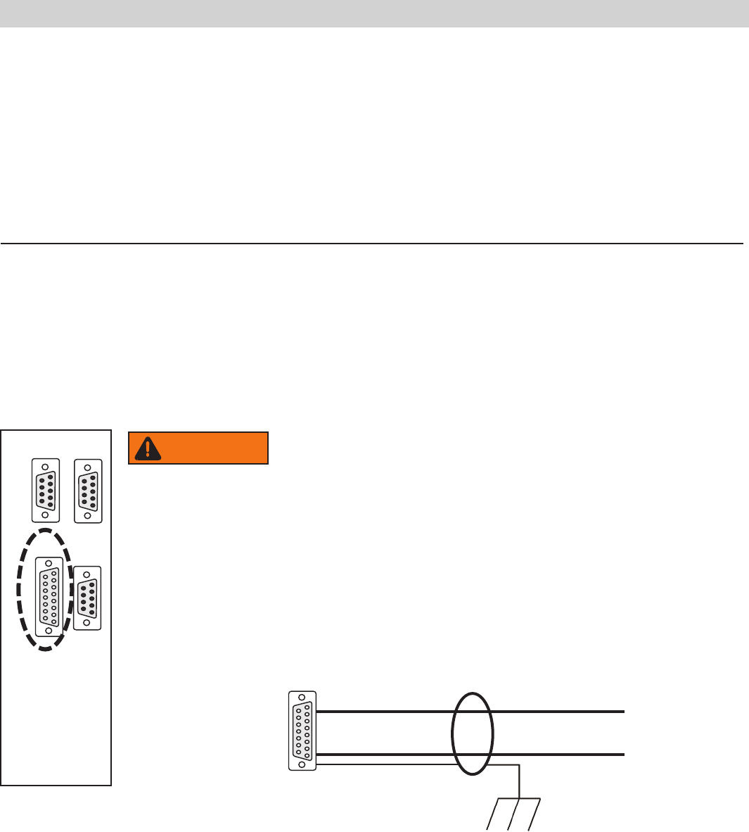
Figure C-1 Analog I/0 Connector
When making your connection to the ThermoFlex Analog I/0
connector, in order to comply with the EMC directive:
• Use a shielded I/0 cable
• Connect the remote end of the cable shield to earth ground.
• Connect cable shield to ThermoFlex end connector.
A I/0 15-pin D-sub
15 conductor cable with shield
Connect shield to earth ground
Connect shield to ThermoFlex connector
1 2 3 4 5
6 7 8 9
1 2 3 4 5
6 7 8 9
1 2 3 4 5
6 7 8 9
8 7 6 5 4 3 2 1
15 14 13 12 11 10 9
RS232 RS485
A I/O REMOTE
SENSOR
8 7 6 5 4 3 2 1
15 14 13 12 11 10 9
Never apply line voltage to any of the connections.
WARNING