ThermoFlex-Manual.pdf - 第121页
Thermo Scientific Appendix C ThermoFlex C-5 Thermo Scientific Analog Input Calibration Figure C-3 Analog Input Calibration Loop xx.x xx.x 9.50 0.50 Ai Hi Ai Hi Ai Lo Ai Lo xx.x C mode rtd1 Flo CAL enter enter enter enter e…

Thermo Scientific
C-4 ThermoFlex
Appendix C
Thermo Scientific
Thermo Scientific
Table 1 Configurable Relay #1 (CodE1)
Error Error Code Factory Default
Low Level (option) LLF Enable 1 (Default)
Tank Overflow o FLo Disable 2
Drip Pan Full (option) driP Disable 4
Low Temp Lo t* Disable 8
High Temp Hi t* Disable 16
Low Flow (option) LoFLo* Enable 32 (Default)
High Flow (option) HiFLo* Disable 64
Low Resistivity (option) Er 28* Disable 128
High Resistivity (option) Er 30* Disable 256
High Pressure Hi P1* Disable 512
Low Pressure Lo P1* Disable 1024
Chiller Fault Any Fault Enable 2048 (Default)
Pump/Chiller Shut Off Status bit(s) Disable 4096
Refrigeration Shut Off Status Bit Disable 8192
Limit Fault (option) PHEr, oL, LPC, HPC, Er 47, Er 48 Enable 16384 (Default)
Sensor Fault Er 23, Er 24, Er 25, Er 26 Disable 32768
external sensor opened or shorted Default Relay Code 1 Display = 18465
(1 + 32 + 2048 + 16384 = 18465)
*Regardless of alarm setting - fault or indicator
Table 2 Configurable Relay #2 (CodE2)
Error Error Code Factory Default
Low Level (option) Add Disable 1
Tank Overflow o FLo Disable 2
Drip Pan Full (option) driP Disable 4
Auto Refill Error (option) rEFiL Disable 8
Low Temp Lo t* Enable 16 (Default)
High Temp Hi t* Enable 32 (Default)
Low Flow (option) Lo FL* Disable 64
High Flow (option) Hi FL* Disable 128
Low Resistivity (option) Er 28* Disable 256
High Resistivity (option) Er 30* Enable 512 (Default)
High Pressure Hi P1* Disable 1024
Low Pressure Lo P1* Disable 2048
Indicator (warning) Any Indicator Disable 4096
PM Timer (option) di, SEr 1 to 6 Disable 8192
Communication Error Er 15, Er 41, Er 42 Disable 16384
Sensor Fault Er 23, Er 24, Er 25, Er 26 Enable 32768 (Default)
external sensor opened or shorted Default Relay Code 2 Display = 33328
(16 + 32 + 512 + 32768 = 33328)
*Regardless of alarm setting - fault or indicator
Thermo Scientific
Appendix C
ThermoFlex C-5
Thermo Scientific
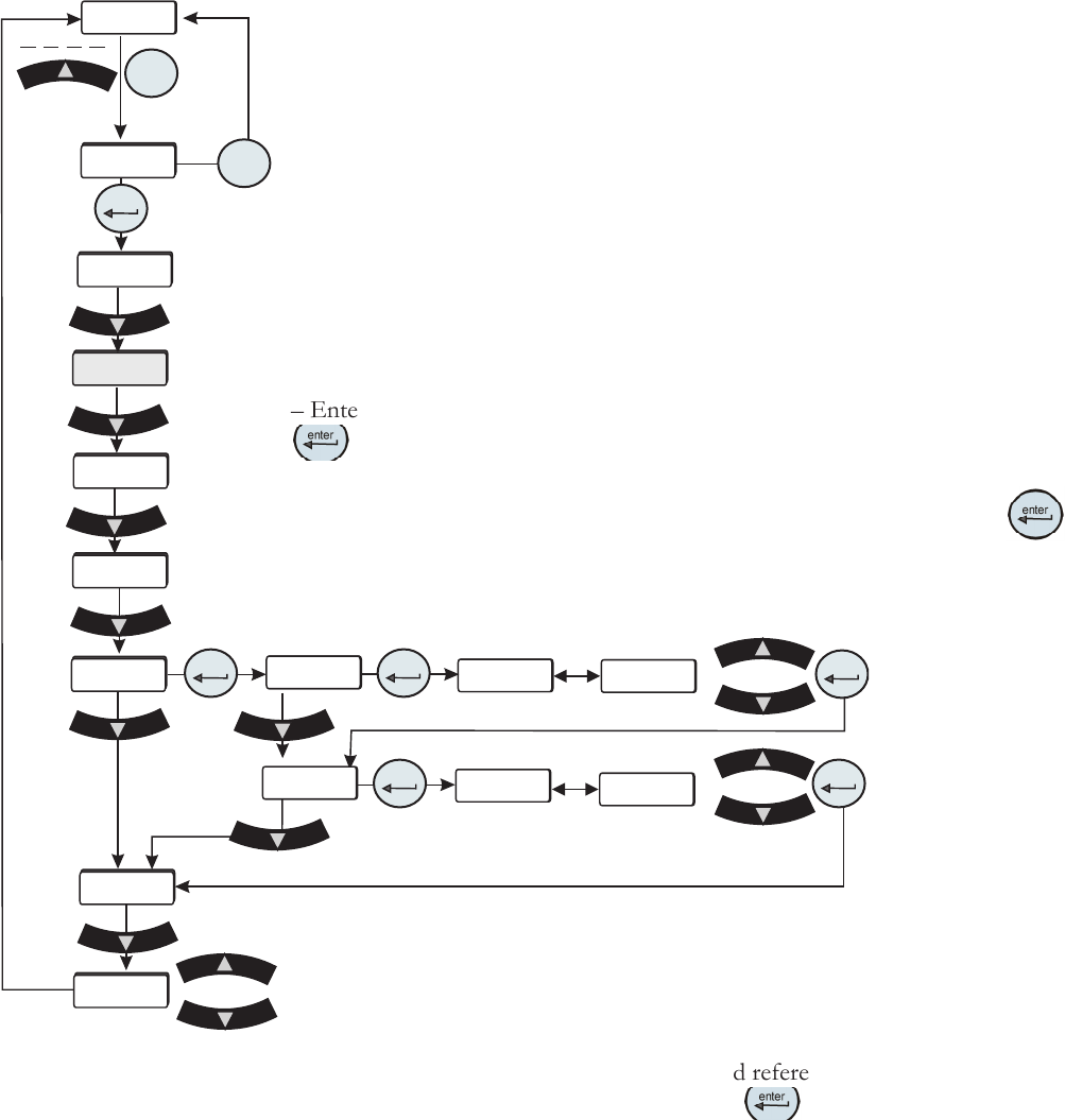
Analog Input Calibration
Figure C-3 Analog Input
Calibration Loop
xx.x
xx.x
9.50
0.50
Ai Hi
Ai Hi
Ai Lo
Ai Lo
xx.x C
mode
rtd1
Flo
CAL
enter
enter
enter
enter
enter
enter
mode
r rtd
A in
Aout1
StorE
PrES1
The analog input uses a 2-point calibration. Depending on how the analog input is
congured Type1, Type2 or Type 3, the HMI will display either volts, millivolts or
milliamps. The calibration procedure is:
– Start with default high and low endpoints each consisting of a voltage/current
value and a theoretical analog input value. This will permit calibration of either
point rst. Both ends must be calibrated for the entire calibration to be valid.
– Connect a 9.50v/0.400mv/20.00ma reference voltage/current source to the
analog input, pins 6 and 15.
– The HMI will display 9.50/0.400/20.00. Use the arrow keys to adjust the display
to match the applied input voltage/current.
– Allow the analog input to stabilize, approximately 10 seconds.
– Enter the measured reference voltage/current using the HMI by pressing the
key. The rmware will use this value and the theoretical analog value and
those from the low end to calculate a linear gain and offset.
– The display will automatically go to the low calibration message. Press
to
calibrate the analog input at the low end.
– Connect a 0.50v/0.050mv/4.00ma reference voltage/current source to the analog
input.
Save calibration
Do not save calibration
– The HMI will display 0.50/0.050/4.00. Use the arrow
keys to adjust the display to match the applied input
voltage/current. Allow the analog input to stabilize,
approximately 10 seconds.
– Enter the measured reference voltage/current using the
HMI by pressing the
key. The rmware will use this
value and the theoretical analog input value and those from
the high end to calculate a linear gain and offset.
– If the gain and offset are acceptable, the calibration is
accepted and the calibration is now valid at the low end.
Otherwise, the calibration is rejected and a bad calibration
error message (Er 16) is displayed.
Thermo Scientific
C-6 ThermoFlex
Appendix C
Thermo Scientific
Thermo Scientific
xx.x
xx.x
9.50
4.50
Ao Hi
Ao Lo
xx.x C
mode
rtd1
Flo
CAL
enter
enter
enter
enter
mode
r rtd
A in
Aout1
StorE
PrES1
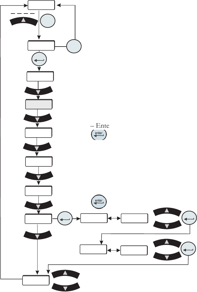
The analog output uses a 2-point calibration. Depending on how the analog
output is congured Type1, Type2 or Type 3, the HMI will display either volts,
millivolts or milliamps. The calibration procedure is:
– Start with default high and low endpoints each consisting of a voltage/current
value and a theoretical DAC value. This will permit calibration of either point
rst. Both ends must be calibrated for the entire calibration to be valid.
– Connect a 9.50v/0.40mv/20.00ma reference voltage/current meter to the DAC
output, pins 6 and 7.
– The HMI will display 9.50/0.40/20.00. Use the arrow keys to adjust the output
to match the display of 9.50v/0.40mv/20.00ma.
– Allow the DAC output and voltage reading to stabilize, approximately 10
seconds.
– Enter the measured reference voltage/current using the HMI by pressing the
key. The rmware will use this value and the theoretical DAC value and
those from the low end to calculate a linear gain and offset.
– The display will automatically go to the low calibration point.
– Use the arrow keys to adjust the output to match the displayed value. Allow the
DAC output and voltage to stabilize, approximately 10 seconds .
– Enter the measured reference voltage/current using the HMI by pressing the
key. The rmware will use this value and the theoretical DAC value and
Analog Output Calibration
those from the high end to calculate a
linear gain and offset.
– If the gain and offset are acceptable,
the calibration is accepted and the
calibration is now valid at the low end.
Otherwise, the calibration is rejected and
a bad calibration error message (Er 16)
is displayed.
Figure C-4 Analog Output Calibration Loop
Save calibration
Do not save calibration