ThermoFlex-Manual.pdf - 第118页
Thermo Scientific C-2 ThermoFlex Appendix C Thermo Scientific Thermo Scientific PIN NAME NOTES DEFINITION 13 REMOTE SETPOINT Note 3 Connect to pin 1 to allow the setpoint to be changed remotely through pin 15 ENABLE REMOTE …
ThermoFlex C-1
Thermo Scientific
Appendix C Analog I/0 and Remote Sensor
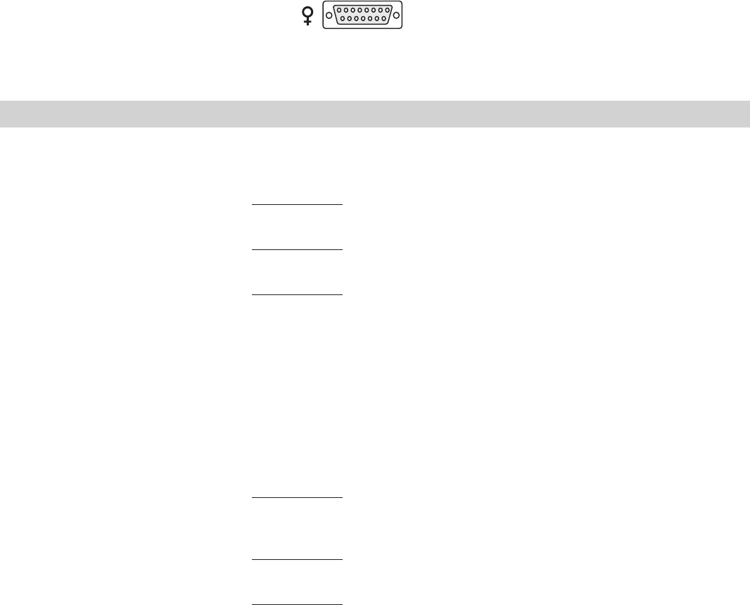
Analog I/O Connector Pinout
Install your analog input/output device to the 15-pin female connector on the rear of the chiller. Analog I/O is
activated using the Setup Loop, see page C-3.
PIN NAME NOTES DEFINITION
1 DIGITAL GROUND Common round connection for pins 12, 13 and 14
2 Not Used
3 LOW LEVEL Note 1 Dry Relay Contact: Reference to pin 11.
(Only if option chosen) Closes if either level switch is in the “low” position for more than 1 second.
4 CONFIGURABLE RELAY 2 Note 1 Dry Relay Contact: Reference to pin 11.
Closes when any configured fault or warning occurs, see Table 2.
5 PUMP ON Note 1 Dry Relay Contact: Reference to pin 11.
Closes when pump is turned on.
Opens when pump is turned off.
6 ANALOG GROUND Common for analog signals (pins 2, 7 and 15)
7 RESERVOIR TEMP OUT Note 2 Analog Voltage Output 0-10VDC, 10mV/°C, or 4-20mA: Reference to pin 6.
OR EXTERNAL SENSOR This voltage output is proportional to the reservoir fluid temperature:
TEMPERATURE IF Default scale= 0–10V (where: 0V = Low Temp Span, 10V = Hi Temp Span)
EXTERNAL SENSOR Optional Range = 10mV/
O
C. (Ex: 200mV = 20°C) (Max Load @ 10V = 5mA)
ENABLED or 4-20mA, 4mA = low temp span, 20 mA = high temp span (maximum output
current = 5mA @10VDC.
8 LOW FLOW Note 1 Dry Relay Contact: Reference to pin 11.
(Only if option chosen) Closes when a low flow occurs while the pump is on. Note: To allow the pump to get up to
speed at startup, the pump runs for 3 - 5 seconds before the low flow sensor is read.
9 CONFIGURABLE RELAY 1 Note 1 Dry Relay Contact: Reference to pin 11.
(Normally Open) Closes when any of the configured faults occur, see Table 1.
10 CONFIGURABLE RELAY 1 Note 1 Dry Relay Contact: Reference to pin 11.
(Normally Closed) Complement of pin 9 (open when pin 9 is closed).
11 RELAY COMMON Common for all relay contacts (pins 3, 4, 5, 8, 9, 10).
12 REMOTE START Note 3 Connect to pin 1 to allow chiller to be remotely turned on/off through pin 14
ENABLE REMOTE START.
Note 1: All relay contacts (except for Pin 10) are normally OPEN when power is off. Pin 10 contacts are normally CLOSED when power is off. Relay
contacts are rated: 24V AC/DC, 2A, <= 0.08 Ohm maximum each or 5A total for all relays combined, 1mA minimum, switching capacity: 48VA/48W
(Resistive load only).
Note 2: Default = 0-10VDC
Note 3: Connect to digital ground (pin 1) using a low resistance connection (gold contact relay).
8 7 6 5 4 3 2 1
15 14 13 12 11 10 9
Thermo Scientific
C-2 ThermoFlex
Appendix C
Thermo Scientific
Thermo Scientific
PIN NAME NOTES DEFINITION
13 REMOTE SETPOINT Note 3 Connect to pin 1 to allow the setpoint to be changed remotely through pin 15
ENABLE REMOTE SETPOINT.
14 REMOTE START Note 3 Connect to pin 1 to turn chiller on. Disconnect to turn chiller off.
Note: Pins 1 and 12 must be connected to allow operation from this pin.
15 REMOTE SETPOINT Note 2, 4 Analog Voltage Input 0-10VDC, 10mV/°C, or 4-20mA: Reference to pin 6.
Apply a DC voltage to this pin to adjust the chiller's setpoint:
Default Range = 0 – 10V (where: 0V = Low Temp Span, 10V = Hi Temp Span)
(Input Impedance > 600K)
Optional Range = 10mV/
O
C. (Ex: 200mV = 20°C) (Max Input Voltage = 10VDC,
or 4-20mA, 4mA = low temp span, 20 mA = high temp span.
Note 1: All relay contacts (except for Pin 10) are normally OPEN when power is off. Pin 10 contacts are normally CLOSED when power is off.
Relay contacts are rated: 24V AC/DC, 2A, <= 0.08 Ohm maximum each or 5A total for all relays combined, 1mA minimum, switching capacity:
48VA/48W (Resistive load only).
Note 2: Default = 0-10VDC
Note 3: Connect to digital ground (pin 1) using a low resistance connection (gold contact relay).
Note 4: Remote setpoint must be enabled, pin 13
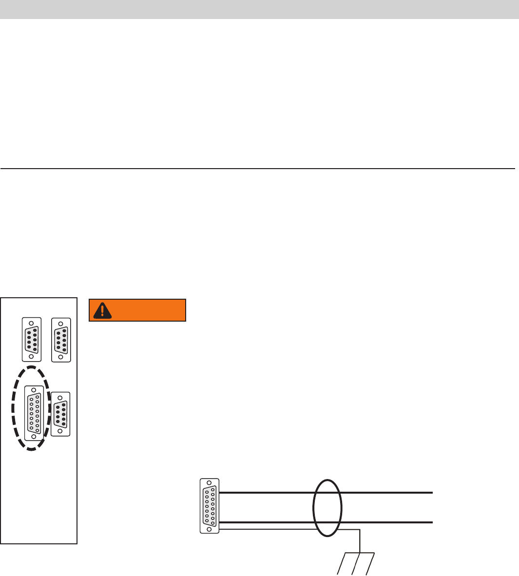
Figure C-1 Analog I/0 Connector
When making your connection to the ThermoFlex Analog I/0
connector, in order to comply with the EMC directive:
• Use a shielded I/0 cable
• Connect the remote end of the cable shield to earth ground.
• Connect cable shield to ThermoFlex end connector.
A I/0 15-pin D-sub
15 conductor cable with shield
Connect shield to earth ground
Connect shield to ThermoFlex connector
1 2 3 4 5
6 7 8 9
1 2 3 4 5
6 7 8 9
1 2 3 4 5
6 7 8 9
8 7 6 5 4 3 2 1
15 14 13 12 11 10 9
RS232 RS485
A I/O REMOTE
SENSOR
8 7 6 5 4 3 2 1
15 14 13 12 11 10 9
Never apply line voltage to any of the connections.
WARNING
Thermo Scientific
Appendix C
ThermoFlex C-3
Thermo Scientific
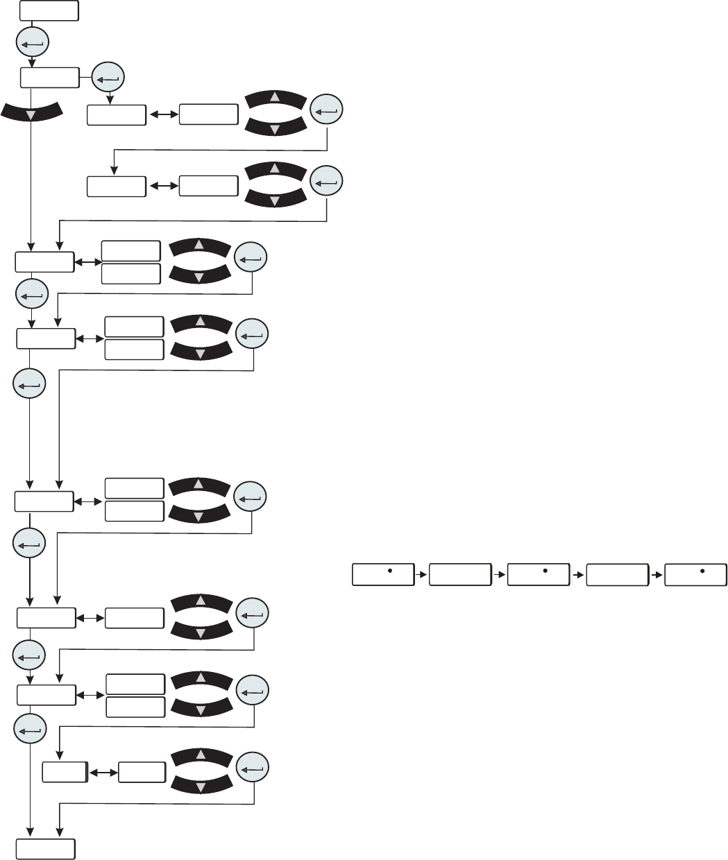
• rELAY is used to congure relay 1 (CodE 1) and
relay 2 (
CodE 2), see Tables 1 and 2 on the next page.
For example: To have just the drip pan, 4, and low
temp, 8, error faults enabled for relay 1 you would
enter their sum, 12, at the
CodE 1 display. To have the
tank overow, 2, the low temp, 16, and high pressure,
1024, error faults enabled for relay 2 you would enter
their sum, 1040, at the
CodE 2 display.
This display depends on your chiller
configuration, see Section 4.
Figure C-2 Analog I/0 Loop
xx. x Cxx. x C xx. x C
xx. x Cxx. x C xx. x C
• r rtd is used to enable/disable the remote temperature
sensor. See Table 3 for pin out information.
Note There is no other indication on the chiller that the
remote sensor is enabled.
• r.Start is used to enable/disable the remote start/stop.
Note Enabling analog I/O remote start/stop disables
the chiller’s local controller start/stop capability. Enabling
analog I/O remote also overrides serial communications
start/stop commands.
• r SEt is used to enable/disable the remote setpoint.
Note When remote setpoint is enabled a ashing dot will
appear on the controller's display as shown below.
• AnAin is used to congure the analog voltage input type.
Type 1: 0 - 10 VDC (Default)
Type 2: 10 mV/°C
Type 3: 4 - 20 mA
• dAC is used to enable/disable the digital to analog
converter. Once enabled, the desired output type can be
selected.
Note The Type display only appears if dAC is set to on.
Type 1: 0 - 10 VDC (Default)
Type 2: 10 mV/°C
Type 3: 4 - 20 mA
rELAY
CodE 1
CodE 2
enter
enter
xx
xx
xxxxx
xxxxx
enter
enter
r rtd
r.Start
r SEt
AnAin
dAC
dAC
----
xx
xx
xx
xx
xx
xx
xx
xx
xx
xx
OFF
OFF
OFF
OFF
on
on
on
on
tYPE1
tYPE1
enter
enter
enter
enter
enter
enter
enter
enter
enter
enter
enter
OPt