ThermoFlex-Manual.pdf - 第126页
Thermo Scientific D-2 ThermoFlex Appendix D Thermo Scientific Thermo Scientific RS-232 COMM RS-485 COMM Pin # Function Pin # Function 1 No connection 1-7 No connection 2 TX 8 T+ 3 RX 9 T - 4 No connection 5 GND = Signal gro…
ThermoFlex D-1
Thermo Scientific
Appendix D NC Serial Communications Protocol
Note Appendix D assumes you have a basic understanding of communications protocols.
Never apply line voltage to any of the connections.
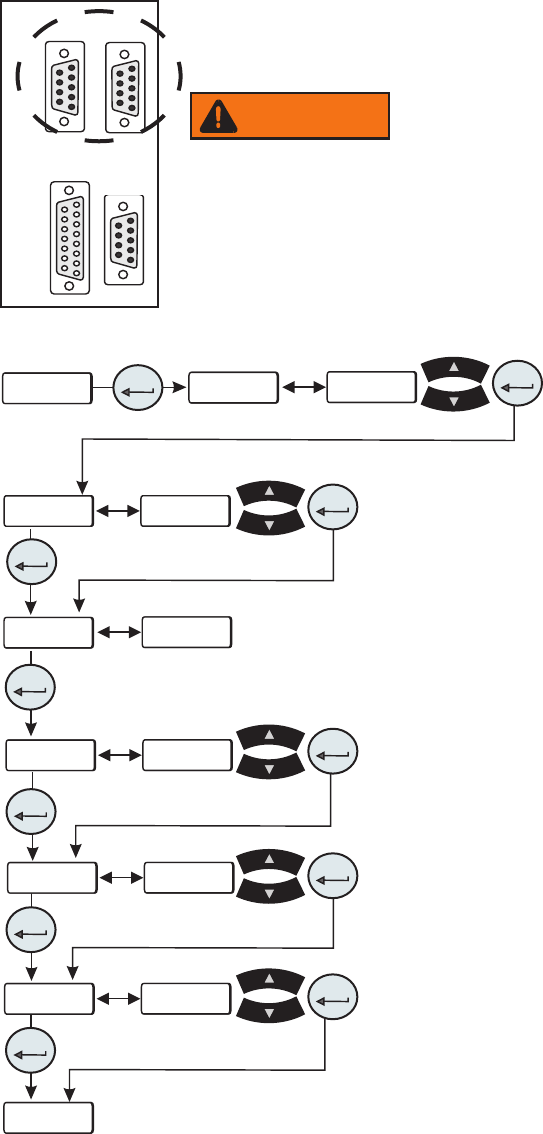
Connect your PC to the applicable connector on the rear of the chiller. Use the Setup Loop,
see Section 4, to enable serial communications.
Note Keypad operation is still available with serial communications enabled.
• SEr is used to enable/disable and to congure
serial communications.
Range:
oFF, rS232, rS485 Default: oFF
This display depends on your chiller
configuration, see Section 4.
Figure D-1 Connectors
Figure D-2 Serial Communications Loop
BAud
StoP
dAtA
PAr
uid
----
SEr
SEr
enter
enter
enter
enter
enter
enter
xx
xx
xx
xx
xx
xx
xxxx
8
xxxx
x
xx
xx
enter
enter
enter
enter
enter
1 2 3 4 5
6 7 8 9
1 2 3 4 5
6 7 8 9
1 2 3 4 5
6 7 8 9
8 7 6 5 4 3 2 1
15 14 13 12 11 10 9
RS232 RS485
A I/O REMOTE
SENSOR
• BAud is used to select the baud rate (speed) for serial
communications.
Range: 9600, 4800, 2400, 1200, 600, or 300 bits per second
Default: 9600
• dAtA is used to display the number of data bits.
Range: Fixed at 8
• StoP is used to indicate the number of stop bits.
Range:
2 or 1 Default: 1
• PAr is used as a means to check for communication errors.
Range:
even, odd, or none Default: none
• u id (chiller id) is used in RS485 only. Identies devices
connected to the RS 485 port.
Range:
1 to 99 Default: 1
Note: To prevent data errors limit the number of chillers to 32.
WARNING

Thermo Scientific
D-2 ThermoFlex
Appendix D
Thermo Scientific
Thermo Scientific
RS-232 COMM RS-485 COMM
Pin # Function Pin # Function
1 No connection 1-7 No connection
2 TX 8 T+
3 RX 9 T-
4 No connection
5 GND = Signal ground
6 - 9 No connection
TX = Transmitted data from controller
RX = Received data to controller.
Hardware Mating Connector
AMP Part# 745492-2 or equivalent
All data is sent and received in binary form, do not use ASCII. In the following pages the
binary data is represented in hexadecimal (hex) format.
The NC Serial Communications Protocol is based on a master-slave model. The master
is a host computer, while the slave is the chiller's controller. Only the master can initiate a
communications transaction (half-duplex). The slave ends the transaction by responding
to the master’s query. The protocol uses RS-232/RS-485 serial interface with the default
parameters: 9600 baud, 8 data bits, 1 stop bit, and no parity. RS-485 offers a slave address
selection, default parameter: 1.
The chiller can be controlled through your computer’s serial port by using the chiller's
standard female 9-pin connection.
Communication cables are available from Thermo Fisher. Contact us for additional
information.
5 4 3 2 1
9 8 7 6
All commands must be entered in the exact format shown in the tables on the following
pages. The tables show all commands available, their format and responses. Controller
responses are either the requested data or an error message. The controller response must
be received before the host sends the next command.
The host sends a command embedded in a single communications packet, then waits for
the controller’s response. If the command is not understood or the checksums do not
agree, the controller responds with an error command. Otherwise, the controller responds
with the requested data. If the controller fails to respond within 1 second, the host should
resend the command.

Thermo Scientific
Appendix D
ThermoFlex D-3
Thermo Scientific
Note All byte values are shown in hex, hex represents the binary values that must be sent to the
chiller. Do not use ASCII.
The framing of the communications packet in both directions is:
Checksum region
Lead char Addr-MSB Addr-LSB Command n d-bytes d-byte 1 ... d-byte n Checksum
Lead char 0xCA (RS-232) 0xCC (RS-485)
Device address is 1 (RS-232)
Addr-msb Most signicant byte of slave address (RS-232: 0)
Addr-lsb Least signicant byte of slave address (RS-232: 1)
Command Command byte (see Table of Commands)
n d-bytes Number of data bytes to follow
d-byte 1 1
st
data byte (the qualier byte is considered a data byte)
... ...
d-byte n n
th
data byte.
Checksum Bitwise inversion of the 1 byte sum of bytes beginning with the most
signicant address byte and ending with the byte preceding the checksum.
(To perform a bitwise inversion, "exclusive OR" the one byte sum with FF
hex.)
When a command has no value associated with it (e.g., REQ ACK), “n d-bytes” will be set to 0.
Values such as temperature and ow are sent as either 2 or 4 byte signed integers, depending on
how they are stored in the controller RAM.
When the controller sends a value, a qualier byte is sent rst, followed by a 2 or 4 byte
integer (the least signicant byte is sent last). The qualier indicates the precision and units of
the value. The host does not send the qualier byte; it must send the value using the correct
precision, units and number of bytes. The host rst inquires about a value it wants to change,
then uses the number of data bytes and the qualier byte it receives to generate the proper
integer to send.
OxCA/OxCC