00193463-01.pdf - 第200页
5 Station extensions User Manual SIPLACE S-25 H M 5.9 Nozzle changer for the 6-segment Collect&Place head Software Version SR.503.xx 04/2002 US Edition 200 5.9.7 Position detection There is a posi tion d etection f i…
User Manual SIPLACE S-25 HM 5 Station extensions
Software Version SR.503.xx 04/2002 US Edition 5.9 Nozzle changer for the 6-segment Collect&Place head
199
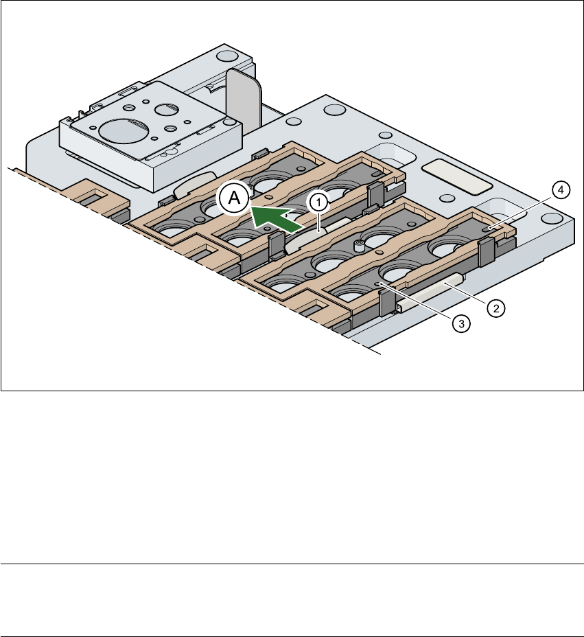
5.9.6 Changing the magazine
Æ To remove the magazine, push the spring hook (item 1 in Fig. 5.9 - 4) away from the magazine.
Lift the magazine out of the carrier.
Fig. 5.9 - 4 Changing the magazine
(1) Spring hook
(2) Retaining clamp
(3) Centering hole
(4) Slot
(A) Push the spring hook away from the magazine 5
PLEASE NOTE
Make sure that you insert the magazine so that the centering pins slide into the centering hole
(item 3) and slot (item 4). 5
Æ Then place the side of the magazine with the centering hole (item 3) and slot (item 4) on the
carrier. The two knobs on the magazine must slide into the retaining clamp (item 2).
Æ Push the spring hook away from the magazine.
Æ Press the magazine so that it lies flat on the carrier, then release the spring hook. The spring
hook must latch into place.
5 Station extensions User Manual SIPLACE S-25 HM
5.9 Nozzle changer for the 6-segment Collect&Place head Software Version SR.503.xx 04/2002 US Edition
200
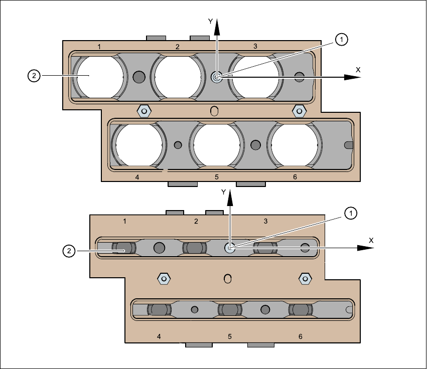
5.9.7 Position detection
There is a position detection fiducial on every magazine. 5
Fig. 5.9 - 5 Nozzle changer - position detection
(1) Positioning fiducial
(2) Position of the nozzles in the magazine with respect to the positioning fiducial
5
User Manual SIPLACE S-25 HM 5 Station extensions
Software Version SR.503.xx 04/2002 US Edition 5.10 Vacuum tooling
201
5.10 Vacuum tooling
Vacuum tooling is another module that is used to increase the placement accuracy for concave
PCBs. The vacuum surface of this device picks up concave PCBs during processing and aligns
them so they are flat. 5
The vacuum tooling module can be used on both single and dual conveyors, and is fitted to the
lifting tables. 5
Description of the functions 5
The PCB is fed to the processing belt, where it is stopped. The lifting table moves up and the vac-
uum circuit for the vacuum tooling device is opened. The PCB is then held in place by the vacuum
tooling device, which is pressed with a spring action against the PCB by the lifting table. This
causes the suction cups of the tooling device to press against the PCB and hold it firmly in posi-
tion. 5
The vacuum channels are vented after placement. The lifting table is lowered, the PCB is re-
leased, and can then be moved on. 5