00193463-01.pdf - 第45页
User Manual SIPLACE S-25 HM 1 Introduction, technical data Software Vers ion SR.503.xx 04/2002 US Edition 1.14 Overview of the modules - vision m odules 45 1.14.2 T echnical dat a - component vision module (s t andard ca…
1 Introduction, technical data User Manual SIPLACE S-25 HM
1.14 Overview of the modules - vision modules Software Version SR.503.xx 04/2002 US Edition
44
1.14 Overview of the modules - vision modules
Each placement system has 1
– two component vision cameras on the placement heads and
– two PCB vision cameras on the underside of the X-axis gantries.
The vision analysis unit is located in the control unit for the placement system and the component
vision module is used to determine: 1
– the precise position of the components at the nozzle and
– the geometry of the package form.
The PCB vision module uses fiducials on the PCBs to determine: 1
– the position of the PCB,
– its rotation angle
– and the PCB delay.
The PCB vision module also uses fiducials on the feeder modules to determine the exact pick-up
position of components, which is particularly important for small components. 1
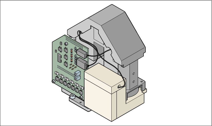
1.14.1 Component vision module (standard camera) on the
12-segment Collect&Place head
1
Fig. 1.14 - 1 Component vision module (standard camera) on the 12-segment Collect&Place head
User Manual SIPLACE S-25 HM 1 Introduction, technical data
Software Version SR.503.xx 04/2002 US Edition 1.14 Overview of the modules - vision modules
45
1.14.2 Technical data - component vision module (standard camera) on the
12-segment Collect&Place head
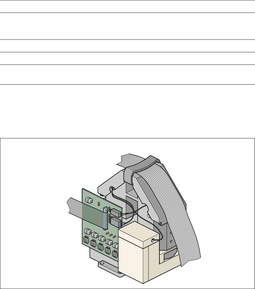
1.14.3 Component vision module (standard camera) on the
6-segment Collect&Place head
1
Fig. 1.14 - 2 Component vision module (standard camera) on the 6-segment Collect&Place head
Component dimensions 0.6 mm x 0.3 mm up to 18.7 mm x 18.7 mm
Range of components 0201 to PLCC44
including BGA, µBGA, flip-chip, TSOP, QFP
PLCC, SO to SO32, DRAM
Min. lead pitch 0.5 mm
Field of vision 24 mm x 24 mm
Illumination method Front-lighting
(3 levels programmable as required)
1 Introduction, technical data User Manual SIPLACE S-25 HM
1.14 Overview of the modules - vision modules Software Version SR.503.xx 04/2002 US Edition
46
1.14.4 Technical data - component vision module (standard camera) on the
6-segment Collect&Place head
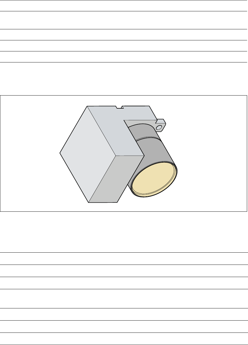
1.14.5 PCB vision module
1
Fig. 1.14 - 3 PCB vision module
1.14.6 Technical data - PCB vision module
1
Component dimensions 0.5mm x 1.0mm to 32mm x 32mm
Component range
0603 to 32mm x 32mm
PLCC, SO, QFP, TSDP, SOT, MELF, CHIP, IC BGA
Minimum lead pitch 0.5 mm
Field of view 24mm x 24mm
Method of illumination Front lighting (3 levels programmable as required)
Fiducials Up to 3 per placement program
Local fiducials Up to 2 per PCB (may be of different types)
Library size Up to 255 fiducial types - system fiducials
≥ 249
Image processing Correlation principle or contour following method
(geometric alignment)
Illumination method Front-lighting
Recognition time per fiducial/ink spot 0.4 s
Field of vision 5.7 mm x 5.7 mm