00193463-01.pdf - 第206页
5 Station extensions User Manual SIPLACE S-25 H M 5.12 DCA v ision module on th e 6-segment Co llect&Place head Software Version SR .503.xx 04/ 2002 US Edition 206 5.12.1 Description of the 6-segment Coll ect&Pla…
User Manual SIPLACE S-25 HM 5 Station extensions
Software Version SR.503.xx 04/2002 US Edition 5.12 DCA vision module on the 6-segment Collect&Place head
205
5.12 DCA vision module on the 6-segment
Collect&Place head
5
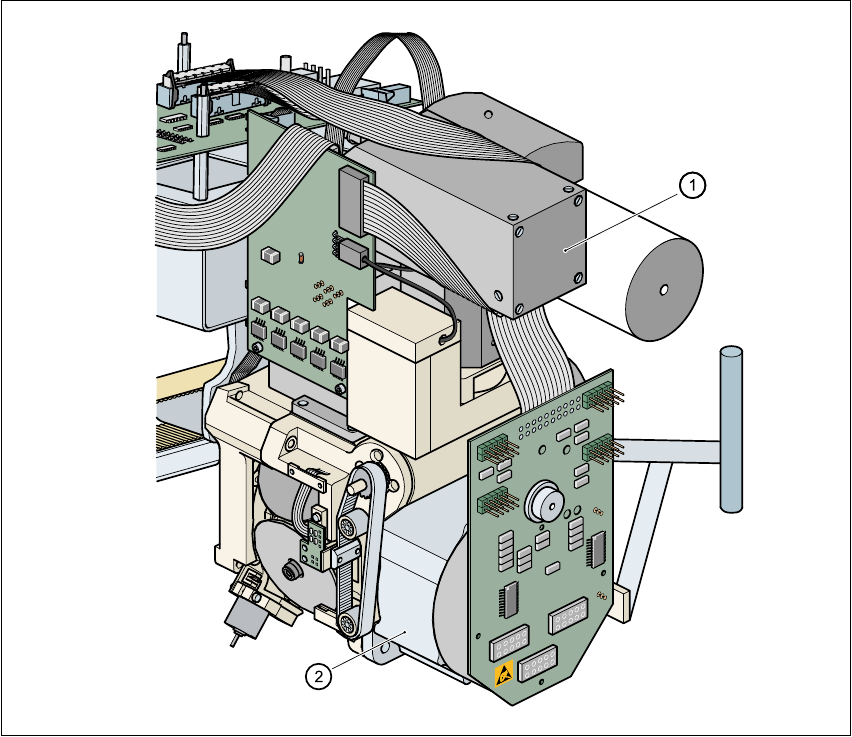
Fig. 5.12 - 1 DCA vision module on the 6-segment Collect&Place head
5
(1) DCA vision module
(2) 6-segment Collect&Place head

5 Station extensions User Manual SIPLACE S-25 HM
5.12 DCA vision module on the 6-segment Collect&Place head Software Version SR.503.xx 04/2002 US Edition
206
5.12.1 Description of the 6-segment Collect&Place head with
DCA vision module
With the DCA vision module, the 6-segment Collect&Place head is able to optically center and
place components of the order of magnitude of 0.6 mm x 0.3 mm to 13 mm x 13 mm. The DCA
package optimizes the speed and accuracy when placing high-speed flip chips and bare die
components.
5.12.2 Technical data for the 6-segment Collect&Place head with
DCA vision module
5
PLEASE NOTE 5
The technical data for the DCA vision module is given in section 5.11.3 on page 204. 5
5
Component range 0201 to 13 mm x 13 mm
Component specification
Max. height
Min. lead pitch
Min. bump pitch
Min. ball/bump diameter
Min. dimensions
Max. dimensions
Max. weight
8.5 mm
0.4 mm
0.2 mm
0.11 mm
0.6 mm x 0.3 mm
13 mm x 13 mm
5 g
Travel of the Z axis max. 16 mm
Programmable placement force 2.4 to 5.0 N
Nozzle types 8xx, 9xx
Max. placement rate 8.500 components/hour
Angular accuracy ± 0.4° / 4
σ
Placement accuracy of the DCA vision module ± 70 µm / 4 σ
User Manual SIPLACE S-25 HM 5 Station extensions
Software Version SR.503.xx 04/2002 US Edition 5.13 Component sensor
207
5.13 Component sensor
5.13.1 Function
The component sensor is fixed to the underside of the casing of the 12-segment Collect&Place
head (see Fig. 5.13 - 2). It measures the height of the nozzle and the height of the nozzle with the
component. The component height is then determined from the two values. The sensor thus also
checks that the component is actually present.
Component heights from 0.1 to 4 mm can be checked. It is also possible to determine whether
the component is in its normal position or is sticking to the nozzle on edge. This requires the dif-
ference between the height and width of the component to be at least 100 µm, i.e. component
sizes 0603 or larger.
5
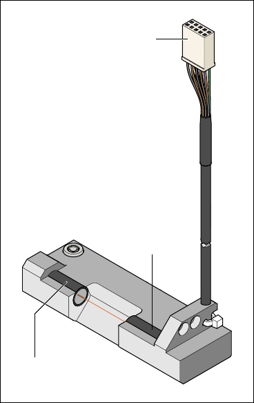
Fig. 5.13 - 1 Component sensor
To the
‘head gantry distribu-
tor’ board
Infrared LED
Phototransistor
(receiver)