00193463-01.pdf - 第25页
User Manual SIPLACE S-25 HM 1 Introduction, technical data Software Vers ion SR.503.xx 04/2002 US Edition 1.7 Electr ical and pneumatic connection points 25 DANGER The placem ent syste m is suppl ied wi th 3 x 400 V or 3…
1 Introduction, technical data User Manual SIPLACE S-25 HM
1.7 Electrical and pneumatic connection points Software Version SR.503.xx 04/2002 US Edition
24
1.7 Electrical and pneumatic connection points
1
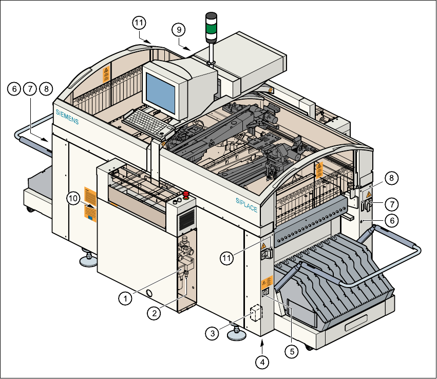
Fig. 1.7 - 1 Electrical and pneumatic connection points on the placement system
(1) Compressed air unit
(2) Connection for compressed air line
(3) Main power filter Z1
(4) Hole for power cable
(5) Service socket
(6) Compressed air supply connection for component changeover table
(7) Power supply connection for component changeover table
(8) Communications connection for component changeover table
(9) LAN connection in the control unit
(10) Main power switch
(11) Control cable connection for matrix tray changer
User Manual SIPLACE S-25 HM 1 Introduction, technical data
Software Version SR.503.xx 04/2002 US Edition 1.7 Electrical and pneumatic connection points
25
DANGER
The placement system is supplied with 3 x 400 V or 3 x 208 V (US version) ± 5%, 50/60 Hz main
power voltage. This means that some parts of the system carry potentially lethal voltages - even
when switched off at the main switch. Incorrect handling of the placement system can therefore
result in death or severe injury or considerable damage to equipment. 1
WARNING
NEVER detach compressed air lines while they are still pressurized. Risk of injury. 1

1 Introduction, technical data User Manual SIPLACE S-25 HM
1.8 Technical data – ratings Software Version SR.503.xx 04/2002 US Edition
26
1.8 Technical data – ratings
1.8.1 Technical data – electrical ratings
1
1.8.2 Technical data – compressed air supply
1
1.8.3 Technical data – compressed air specification
Maximum particle size by density, based on ISO/DIS 8573-1 (class 1) 1
1.8.4 Technical data – noise emissions
1
1
1.8.5 Technical data – permissible ambient factors
1
Supply voltage 3 x 400 VAC ± 5 %; 50/60 Hz (Europe)
3 x 208 VAC ± 5 %; 50/60 Hz (U.S.A.)
3 x 200 VAC ± 5 %; 50/60 Hz (Japan)
Fuses 3 x 16 A (3 x 400 VAC, 3 x 208 VAC, 3 x 200 VAC)
Total connected load 5 kVA
Total power 2 kW
Power failure up to 20 msec
Compressed air pressure Min. 5.5 bar, max. 8 bar, 1/2" connecton
Compressed air consumption 400 Nl/min.
Operating pressure 5.2 bar (fixed)
Particle size 0.1 µm
Particle density 0.1 mg/m³
Maximum oil content (class 1) Particle density 0.01 mg/m³
Pressure dewpoint (class 4) Dewpoint +3°
Max. noise emission 74dB(A)
Room temperature Between 15°C and 35°C
Atmospheric humidity 30 to 80%
(but no higher than 45% on average in order to prevent
any possibility of condensation on the machine).