00193463-01.pdf - 第75页
User Manual SIPLACE S-25 HM 2 Operational Safety Software Vers ion SR.503.xx 04/2002 US Edition 2.1 Safety instruc tions 75 2.1.12 Securing the placement mac hine to preve nt it slipping In areas with an earthquak e risk…
2 Operational Safety User Manual SIPLACE S-25 HM
2.1 Safety instructions Software Version SR.503.xx 04/2002 US Edition
74
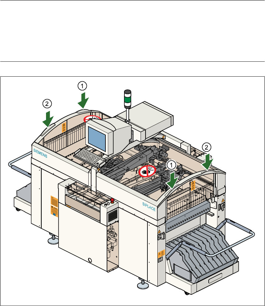
PLEASE NOTE
To open or close the protective covers, hold the recessed grips with both hands (see points (1)
and (2) in Fig. 2.1 - 11). This “two-handed operation” will prevent any risk of injuring your hands.
You will also avoid tilting the protective covers during opening or closing, which would place an
excessive load on the guides. 2
Fig. 2.1 - 11 Two-handed operation
(1) Left hand
(2) Right hand
User Manual SIPLACE S-25 HM 2 Operational Safety
Software Version SR.503.xx 04/2002 US Edition 2.1 Safety instructions
75
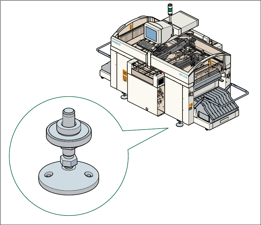
2.1.12 Securing the placement machine to prevent it slipping
In areas with an earthquake risk, it is essential to secure the placement machine to prevent it slip-
ping. 2
Two holes for M8 bolts are provided in the machine feet for this purpose. 2
Æ Use the bolts to fix the placement machine to the floor as shown in the diagram below.
Fig. 2.1 - 12 Securing the placement machine to prevent it slipping

2 Operational Safety User Manual SIPLACE S-25 HM
2.1 Safety instructions Software Version SR.503.xx 04/2002 US Edition
76
2.1.13 Safety instructions for processing capacitors based on powdered metal
There is a risk associated with processing capacitors based on powdered metal (e.g. tantalum). 2
The risk is that 2
– An exothermic reaction, i.e. a sudden build-up of heat, may occur if these components are
damaged. If the ambient conditions are unfavorable, and depending on the capacitance, this
build-up of heat can cause damage.
– This effect can occur when these components are cut.
Please contact your suppliers to clarify whether the components that you handle are affected. 2
In extremely rare cases, this risk can occur in the tape cutter of SIPLACE machines, with the re-
mote possibility of causing a smoldering fire in the waste tape. 2
The ambient conditions are unfavorable if: 2
(1) The components remain on the tape while the set tape cycle is checked (since the operator
can cycle the feeder onward without removing components during this check).
(2) The components remain on the tape, e.g. due to a tear in the cover foil.
(3) The components remain on the tape, and the components or tape do not conform to the
specification, thus increasing the pick-up error rate.
Please follow the instructions given below to minimize the risk when placing capacitors based on
powdered metal. 2
(1) If the component tape is cycled onward manually, the operator must remove any components
remaining in the tape pocket.
(2) If the cover foil tears, the operator must remove any components remaining on the tape.
(3) The waste tape container must be emptied regularly (recommended interval: every hour).
2
CAUTION
To avoid the risk, it is essential to use only feeders that
have been approved for placing such components,
namely:
Article no.: 00141117-01 Model E
Article no.: 00141118-01 Model C/D 2
2
The feeders are labeled as shown
below:
2
Approved for
capacitors based on
metal-powder
Freigegeben für
Kondensatoren auf
Metallpulver-Basis