00193463-01.pdf - 第33页
User Manual SIPLACE S-25 HM 1 Introduction, technical data Software Version SR.503.xx 04/2002 US Edition 1.11 Overview of the modules - controls 33 1.1 1.2 Des cription All the c ontr ols can be reach ed by a 1.6 0 m tal…
1 Introduction, technical data User Manual SIPLACE S-25 HM
1.11 Overview of the modules - controls Software Version SR.503.xx 04/2002 US Edition
32
1.11 Overview of the modules - controls
1.11.1 Controls
1
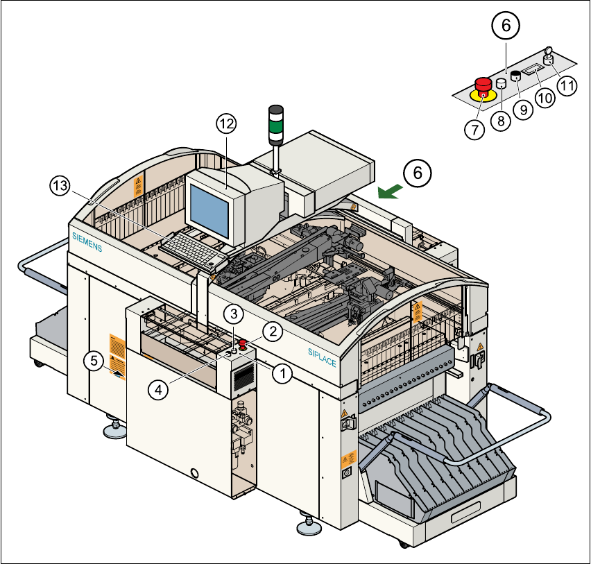
Fig. 1.11 - 1 Overview of the modules - controls
(1) Operator panel, input conveyor (2) Emerg. stop mushroom-head push-button
(3) Start button (white) (4) Stop button (black)
(5) Main power switch (6) Operator panel, output conveyor
(7) Emerg. stop mushroom-head push-button (8) Start button (white)
(9) Stop button (black) (10) Component counter
(11) Key-operated switch (12) Touchscreen monitor
(13) Keyboard with trackball 1
User Manual SIPLACE S-25 HM 1 Introduction, technical data
Software Version SR.503.xx 04/2002 US Edition 1.11 Overview of the modules - controls
33
1.11.2 Description
All the controls can be reached by a 1.60 m tall person. 1
Main switch 1
The main switch is used to switch the power supply to the placement system on and off. 1
RISK OF DEATH
Some parts inside the placement system carry potentially lethal voltages - even when switched off
at the main switch. 1
Key switch 1
In normal mode, the key switch is set to "0". The key should be removed and kept in a safe place.
It must only be turned to position "I" (set-up mode) by authorized personnel, and then only for cer-
tain maintenance and servicing work. 1
Stop button 1
This button is used to stop the placement system. 1
Start button 1
This button starts the placement system after it has been switched on or after faults have been
eliminated. 1
EMERGENCY STOP mushroom-head push-button 1
The emergency stop mushroom-head push-button latches in the ON position when pressed. The
power supply to the gantry axes, the components change-over tables, conveyors, and used tape
cutters is interrupted and the voltage supplied to the star axes of the placement heads is reduced.
Turn the button to release it. 1
Component counter 1
The component counter displays the number of components processed. 1
Station computer, monitor and keyboard 1
The station computer, monitor and keyboard are mounted on a pivoting console on the placement
system’s central cross-beam. The station computer is a desktop model with a Pentium processor.
The operating system is WINDOWS NT 4.0. The SIPLACE graphical user interface, which is
based on the Windows standard, is used to operate and monitor the placement system.
1 Introduction, technical data User Manual SIPLACE S-25 HM
1.11 Overview of the modules - controls Software Version SR.503.xx 04/2002 US Edition
34
A 15" color touch screen monitor with a resolution of 1024 x 768 pixels provides the screen dis-
play. Both the keyboard and the touch screen can be used to enter data, and the ultra-flat IBM-
compatible PC keyboard incorporates a trackball for controlling the mouse. 1
Indicator lamps 1
The sequence of colors is white - green - white. These lamps are used to signal operating statuses
and malfunctions of the placement system. 1
Component barcode reader 1
There is a compartment for the Datalogic DL 910 component barcode reader between the monitor
and keyboard. The barcode reader enables the components to be set up and topped up quickly
and reliably. 1
1.11.3 Ergonomic arrangement of the controls
Figure 1.11 - 1 on page 32 provides an overview of the position of the controls, which are subdi-
vided into the following groups: 1
Operating panel on the PCB input side with 1
– Start button
– Stop button
– Emergency stop mushroom-head push-button
– Main switch (on the left-hand side)
Operating panel on the PCB output side with 1
– Emergency stop mushroom-head push-button
– Start button
– Stop button
– Component counter
–Key switch
Console on the central cross-beam with 1
– Station computer
– Touchscreen
– Keyboard and
– Component barcode reader (option)