Cognex_Scanner_HS-60_HF_X-_D_S_F -05.pdf - 第33页
2 Assembly instructions Special design Cognex Scanner SIPL ACE HS-60 / HF-serie s / X-series / D-series / S / F 06/2008 Edition 35 2.6 Safety instructions WA R N IN G The safety in structions fr om the "Op erational…
2 Assembly instructions Special design Cognex Scanner SIPLACE HS-60 / HF-series / X-series / D-series / S / F
06/2008 Edition
34
For four scanners: 2
– 4 Cognex scanner Dataman 100
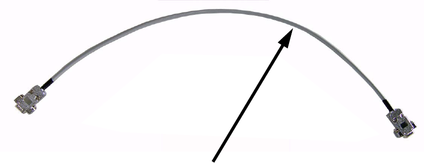
– 4 Interface cables for Dataman 100 (03062979-xx)
– 2 Holding bracket(s) for scanner – upper side – premounted
and
2 holding bracket for scanner – lower side – premounted
– 8 Hexagon socket screws M3 x 5 mm
– 8 Washers ø 7,0 mm
2
2.5 Necessary tools
– Set of hexagon socket spanners
– Set of screw drivers
– Cable ties
– Cable clips
–Side cutter
– Lintfree cloths
– Ethylalcohol for cleaning
2
2
2
Interface cable for Dataman 100

2 Assembly instructions Special design Cognex Scanner SIPLACE HS-60 / HF-series / X-series / D-series / S / F
06/2008 Edition
35
2.6 Safety instructions
WARNING
The safety instructions from the "Operational safety" chapter of the user manual and servicing in-
structions take precedence over these instructions. 2
The SIPLACE placement machines are supplied with main power voltage.
Consequently parts of these systems carry dangerous voltages! This voltage is present at certain
modules inside the machine base, even when the machine is switched off at the main power
switch.
Incorrect handling of the placement machine or touching live parts of the machine can result in
death or severe injury, and considerable damage to equipment.
BEFORE starting any work, shut down the operating system correctly, then switch the machine
OFF at the main power switch and disconnect from the main power supply. In addition, the com-
pressed air supply must be switched off at the compressed air unit's main valve in the machine
base and vented by actuating the needle valve on the compressed air unit.
There is DANGER for heart pacemaker wearers in the vicinity of the linear motors, as described
in detail in the "Special safety instructions for working in the vicinity of strong magnetic fields"
section of the user manual and service manual.
Always follow the accident prevention regulations, DIN or other standards and special safety
rules applicable in your country.
Pay attention to the information concerning residual voltages in the Operational Safety chapter.
Follow the ESD regulations as described in the operational safety section of the operating
instructions.
During the retrofit, always secure the machine to prevent access by other people and to prevent
it being switched on again as described in the "Lock out and tag out procedure" in the user man-
ual.
Working with the SITEST program further increases the risk of accident.
The SITEST program must only be used by authorized and trained personnel.
2
2
2.6.1 Definitions
2
Note 2
2
2
2 Assembly instructions Special design Cognex Scanner SIPLACE HS-60 / HF-series / X-series / D-series / S / F
06/2008 Edition
36
2.7 Hardware installation
2
The depth of focus of the Cognex scanner is 16 mm. Thereby the distance between the scanner
and the board has not to be exactly 40 mm (upper side) or 65 mm (lower side)(may vary from
angle position and machine typ). 2
Run the cables that they can’t be damaged by the width adjustment of the conveyor and that they
do not disturb the PCB transport. 2
2
The installation is shown at an X4 with single conveyor on the right side. The installation into a
double conveyor machine has to be done analogically. 2
o Shut down the machine and switch off the main switch.
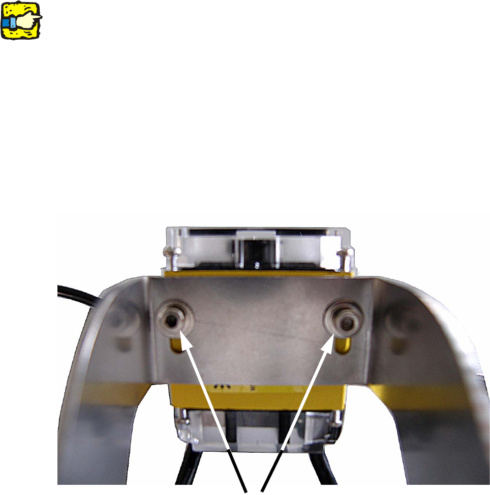
o Mount the Cognex scanner(s) with 2 washers ø 7,0 mm and 2 M3 x 5 mm screws. Therefore
put at first the 7,0 mm washer on the screw and then fix the scanner to the bracket.
2
o Adjust the focus of the scanner depending on machine type or angle adjusting. Place the brak-
ket with the scanner on the final position and measure the distance from the objective to the
PCB- Surface with a measuring tape.
Open the 4 screws of the objective cover and adjust the distance to the PCB- Surface (40 mm
or 65 mm). Then fasten the cover with the 4 screws again.
Mounting of the scanner