YSM40 Mainte_E.pdf - 第25页
xxiii Safety instructions Potential hazard Could cause machine damage (collisions with head, etc.). T o avoid hazard V erify that no objects have been placed on the batch change carrier's (for YSM40 and Z:LEX (YSM20…
xxii
Safety instructions
Potential
hazard
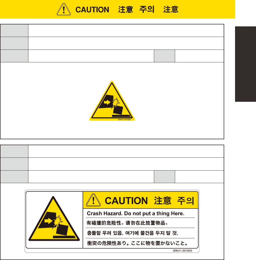
Could cause machine damage (collisions with head, etc.).
To avoid
hazard
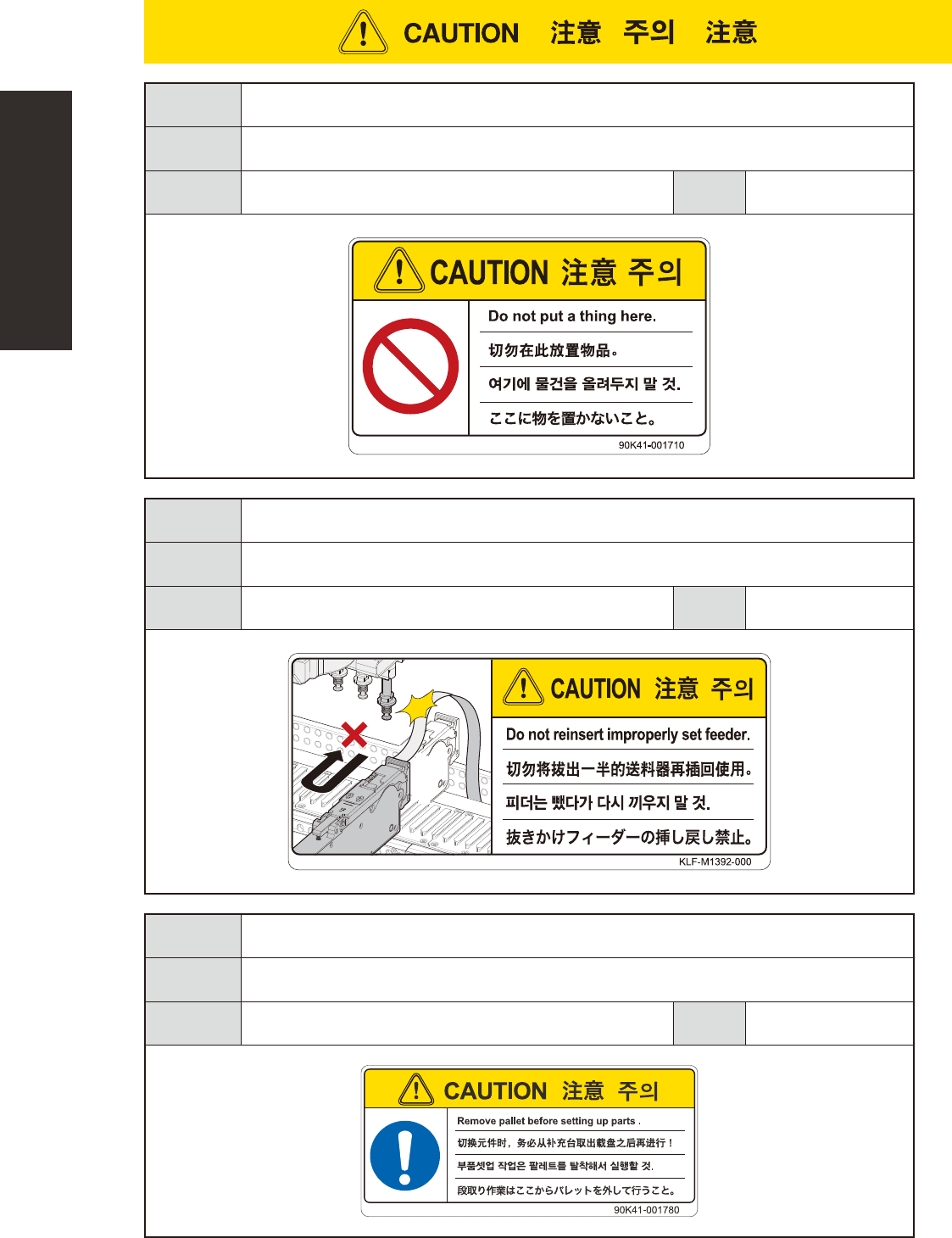
Verify that no objects have been placed on the batch change carrier's (for YSM40) top cover.
Applicable
machines
Batch change carrier (YSM40)
Case
Setup
Potential
hazard
The carrier tape could make contact with the head, possibly causing machine damage.
To avoid
hazard
When a feeder is extracted from its loaded position, be sure that the feeder has been completely
extracted before pressing it back into its loaded position.
Applicable
machines
YSM40
Case
Setup
Potential
hazard
Pallet may drop if setting up parts on the parts supply station.
To avoid
hazard
Remove pallets before setting up parts.
Applicable
machines
cATS (YSM40)
Case
Setup
xxiii
Safety instructions
Potential
hazard
Could cause machine damage (collisions with head, etc.).
To avoid
hazard
Verify that no objects have been placed on the batch change carrier's (for YSM40 and Z:LEX (YSM20))
top cover.
Applicable
machines
Batch change carrier (YSM40, Z:LEX (YSM20))
Case
Setup
Potential
hazard
Could cause machine damage (collisions with head, etc.).
To avoid
hazard
Verify that no objects have been placed on the batch change carrier's (for YSM40 and Z:LEX (YSM20))
top cover.
Applicable
machines
Batch change carrier (YSM40, Z:LEX (YSM20))
Case
Setup
xxiv
Safety instructions
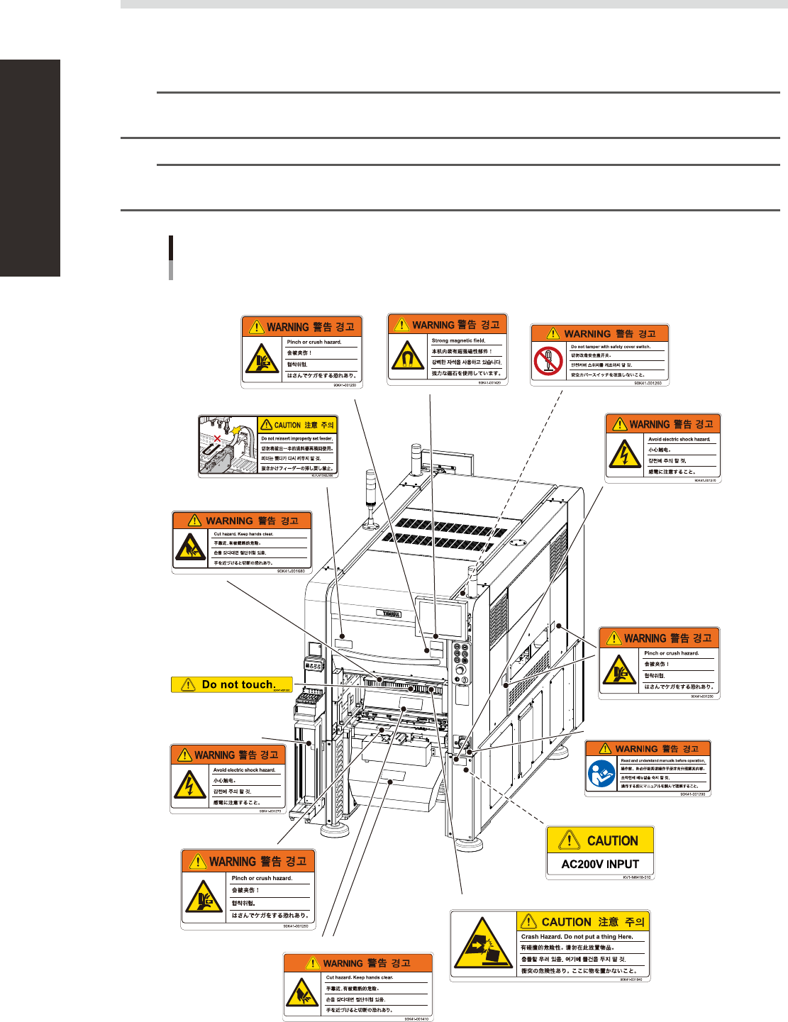
3.4 Label positions
Thefollowingwarning/cautionlabelsareattachedtotheYAMAHAproductstoensuresafeandcorrectuse.
Checkthattheinformationoneachlabelisclearlylegibleandcomplywiththeinstructions.
Forsafetyprecautionsotherthanthoseonthelabelsshowninthissection,seetheinstructionsin"1.Safety".
n
NOTE
Basically, labels are attached to the positions shown below, although they may differ slightly depending on the
machine model.
n
NOTE
When connecting power to this equipment, refer to "Power connection terminals" described in the appendix of the
maintenance manual or user's manual.
Warning/caution labels
Front
■ Top of cutter slope
■ Top of cutter slope
■ Open/close cover
(front and rear sides)
■ Open/close cover inner side
(front and rear sides)
■ Open/close cover
(front and rear sides)
■ At panel
■ Feeder setup section
(front and rear sides)
■ Panel inner side
■ Cutter section
■ Cutter section
■ Conveyor opening
(front and rear sides,
right and left sides)
■ Main switch
93201-N5-10