Nordson_EFD_OptiSure_Operating_Manual.pdf - 第52页
OptiSure Automated Optical Inspection 52 www.nordsonefd.com info@nordsonefd.com +1-401-431-7000 Sales and service of Nordson EFD dispensing systems are available worldwide. T o Use Arr ow Check Point in a Program (Mea. W…
OptiSure Automated Optical Inspection
51www.nordsonefd.com info@nordsonefd.com +1-401-431-7000 Sales and service of Nordson EFD dispensing systems are available worldwide.
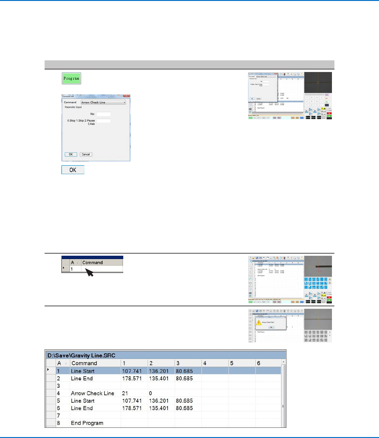
To Use Arrow Check Line in a Program (Mea. Width Example for Verifying Line Width)
# Click Step Reference Image
1
> ARROW CHECK
LINE >
>
• Click the PROGRAM tab.
• Insert commands to dispense a line
directly over the line on the workpiece
template.
NOTE: The complete example
program is provided below.
• Jog the camera to a location on the
line where you want the system to
check the width of the middle of a line
section.
• Insert an ARROW CHECK LINE
command and enter parameters as
follows:
- Enter the number (No.) of the mark
image created in the previous
procedure.
- Select the action you want the
system to take if the measured line
section is above the Max value
or below the Min value specified
for the mark image (step 7 on
page49). Refer to “Arrow Check
Line” on page72 for details.
• Click OK.
2 • Under the Arrow Check Line
command, insert Line Start and Line
End commands that include the
coordinates for the start and end
points of the line you want the system
to check.
When the system executes the Arrow Check Line command and
finds an unacceptable line section, it takes the action specified by the
Stop, Skip, Pause, Ask parameter. Refer to “Arrow Check Line” on
page72 for details.
NOTE: The complete example program is provided below.
Using the Arrow Types (continued)
Mea. Width Example for Verifying Line Width (continued)
Example program that contains an Arrow Check Line command for verifying line width
OptiSure Automated Optical Inspection
52 www.nordsonefd.com info@nordsonefd.com +1-401-431-7000 Sales and service of Nordson EFD dispensing systems are available worldwide.
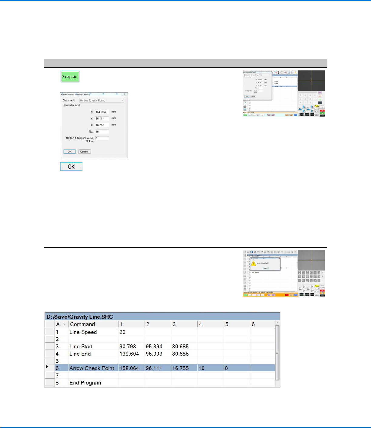
To Use Arrow Check Point in a Program (Mea. Width Example for Verifying Line Width)
# Click Step Reference Image
1
> ARROW CHECK
POINT >
>
• Click the PROGRAM tab.
• Insert commands to dispense a line
directly over the line on the workpiece
template.
NOTE: The example program is
provided below.
• Jog the camera to a location on the
line where you want the system to
check the width of a section of the
line.
• Insert an ARROW CHECK POINT
command and enter parameters as
follows:
- Enter the number (No.) of the mark
image created for the line in the
previous procedure.
- Select the action you want the
system to take if the measured line
section is above the Max value
or below the Min value specified
for the mark image (step 7 on
page49). Refer to “Arrow Check
Point” on page71 for details.
• Click OK.
When the system executes the Arrow Check Point command and
finds an unacceptable line section, it takes the action specified by the
Stop, Skip, Pause, Ask parameter. Refer to “Arrow Check Point” on
page71 for details.
NOTE: The complete example program is provided below.
Example program that contains an Arrow Check Point command for verifying line width
Using the Arrow Types (continued)
Mea. Width Example for Verifying Line Width (continued)
OptiSure Automated Optical Inspection
53www.nordsonefd.com info@nordsonefd.com +1-401-431-7000 Sales and service of Nordson EFD dispensing systems are available worldwide.
Mea. Width Example for Dispense Width Adjustment
Mea. Width (Measure Width) is an OptiSureAOI feature that can be used in tandem with the Arrow Check Point,
Auto Speed Setup, and Auto Speed commands to specify the desired width for a line and then cause the system to
automatically adjust the speed of the dispenser to maintain that desired line width for subsequent dispenses.
PREREQUISITES
To learn how to use this feature, draw two lines of different thicknesses on a sheet of white paper and use it as a
workpiece.
To Create a Mark Image for the Desired Line Width
# Click Step Reference Image
1
>
>
• Jog the camera to a location near the
beginning of the line.
• Click SET MARK, then drag to position
the red box over a portion of the
thinner line.
2
>
• Click a socket in the Mark Library to
save the mark, then click TEMPLATE
when the Template Match window
appears.
The system saves the image in the
Mark Library.
3
>
• Click the ARROW icon.
• In the Primary View screen, right-click
and select ADD NEW ARROW.
The system adds an arrow to the
screen.
4
1.
2.
3.
• Use the mouse to drag the arrow to
the line:
- To move the entire arrow, click and
drag the middle box (item 1).
- To elongate or shorten the arrow,
click and drag the arrow point
(item2) or the upper box (item 3).
Continued on next page
Using the Arrow Types (continued)