Nordson_EFD_OptiSure_Operating_Manual.pdf - 第74页
OptiSure Automated Optical Inspection 74 www.nordsonefd.com info@nordsonefd.com +1-401-431-7000 Sales and service of Nordson EFD dispensing systems are available worldwide. AppendixA, Command Function Refer ence (contin…
OptiSure Automated Optical Inspection
73www.nordsonefd.com info@nordsonefd.com +1-401-431-7000 Sales and service of Nordson EFD dispensing systems are available worldwide.
Auto Speed Setup
Click Function
Double-click
address and
select from drop-
down menu
Used in tandem with the Mea. Width option of the OptiSureAOI feature, this command defines the allowable
line speeds and widths for the Auto Speed command.
NOTE: This command is present in the drop-down menu only when the main.bas file has been added to the
D:\ever_sr directory. The main.bas file is required for the dispense width adjustment feature.
Parameter Description
Max. Speed The maximum line speed for the dispenser.
NOTE: This value cannot exceed the maximum line speed shown in the specifications
section of the robot manual.
Min. Speed The minimum line speed for the dispenser.
NOTE: This value cannot exceed the maximum line speed shown in the specifications
section of the robot manual.
Max. Width The maximum width allowed for the line.
Min. Width The minimum width allowed for the line.
Laser Profile
Click Function
Double-click
address and
select from drop-
down menu
Used in tandem with Laser Program to start or stop laser measurement. When turned ON, the system
uses the laser to measure and record the profile (displacement or thickness) of a fluid or a workpiece. The
resulting graph and measurements (data points) are exported as a *.JPEG and a *.CSV file, respectively.
When Laser Profile turns ON, the Laser Profile window opens to show the measurement data in real time.
In the Laser Profile window, you can enter threshold (tolerance) values and then enable them to cause the
system to check the laser measurements against the threshold values. If a measured value is outside the
threshold range, the system takes the action specified by the selected Stop, Skip, or Pause radio button in
the Laser Profile window. Refer to “To Check Laser Measurements Against Threshold Values” on page67
for details.
NOTES:
• This command applies to PROPlus/L and PRO/L systems only.
• Refer to “To Measure and Record the Profile of a Fluid or a Workpiece” on page63 for an example of
how to use this command in a program.
• The Laser Program command tells the system which laser measurement settings program to use. Refer to
“Laser Program” on page74 for details.
Setting Description
0 Off Turns Laser Profile OFF, stopping laser measurement.
1 On Turns Laser Profile ON, starting laser measurement and opening the Laser Profile
Window. The Laser Profile window can be closed and reopened during active
measurement.
AppendixA, Command Function Reference
(continued)
OptiSure Automated Optical Inspection
74 www.nordsonefd.com info@nordsonefd.com +1-401-431-7000 Sales and service of Nordson EFD dispensing systems are available worldwide.
AppendixA, Command Function Reference
(continued)
Laser Program
Click Function
Double-click
address and
select from drop-
down menu
Specifies the laser measurement settings program to use when the laser is measuring and recording a fluid
or workpiece profile. Laser programs are edited in the CL-NavigatorN software. Program numbers 1–3
contain the following default, pre-programmed laser programs:
• 1. Displacement (Non-Transparent)
• 2. Displacement (Transparent)
• 3. Thickness (Transparent)
Program numbers 0 and 4–7 are programmed by the user.
NOTES:
• This command applies to PROPlus/L and PRO/L systems only.
• Laser programs 1–3 can be user-edited via the CL-NavigatorN software.
• Refer to “To Measure and Record the Profile of a Fluid or a Workpiece” on page63 for an example of
how to use this command in a program.
• The Laser Profile command starts and stops laser measurement. Refer to “Laser Profile” on page73 for
details.
Parameter Description
0-7 Sets the CL-NavigatorN laser program to use when laser measurement and recording is
turned on.
Measure Width
Click Function
Double-click
address and
select from drop-
down menu
Used in tandem with the Mea. Width option of the OptiSureAOI feature, this command causes the system
to measure the width of a dispensed line, as identified by its Side number, against the Max Width and Min
Width values specified in the Auto Speed Setup command.
NOTE: This command is present in the drop-down menu only when the main.bas file has been added to the
D:\ever_sr directory. The main.bas file is required for the dispense width adjustment feature.
Parameter Description
Side A number assigned to the dispensed line to measure (refer to “Auto Speed” on page72
for a diagram that explains this parameter).
Pattern No The mark image number that defines the maximum and minimum allowable widths for a
line.
Move To
Click Function
Double-click
address and
select from drop-
down menu
Moves the tip to the specified XYZ coordinates.
NOTE: This command is present in the drop-down menu only when the main.bas file has been added to the
D:\ever_sr directory. The main.bas file is required for the dispense width adjustment feature.
Parameter Description
x The X coordinate you want to move the tip to.
y The Y coordinate you want to move the tip to.
z The Z coordinate you want to move the tip to.
OptiSure Automated Optical Inspection
75www.nordsonefd.com info@nordsonefd.com +1-401-431-7000 Sales and service of Nordson EFD dispensing systems are available worldwide.
Positional Checking
Click Function
Double-click
address and
select from drop-
down menu
Used in tandem with the Step & Repeat Block command to cause the camera to evaluate the dispensed
dots on an array against user-specified X and Y offsets: If a dispensed dot fits within the specified offsets, it
passes; if not, it fails. If Save Image under System Setup > Other is checked, the system also takes screen
captures of all dispensed dots and saves the image files in the D:\ AOIIMAGE directory. Each image file
includes details about the dispensed dot, including diameter and XY offset values.
Refer to “Positional Checking Example” on page27 for an example of how to use this command in a
program.
Parameter Description
0 Off, 1 On Turns Positional Checking OFF or ON.
Offset X In the X direction, the maximum allowable deviation of an inner dot from the larger
circle.
Offset Y In the Y direction, the maximum allowable deviation of an inner dot from the larger
circle.
Step & Repeat Block
Click Function
Double-click
address and
select from drop-
down menu
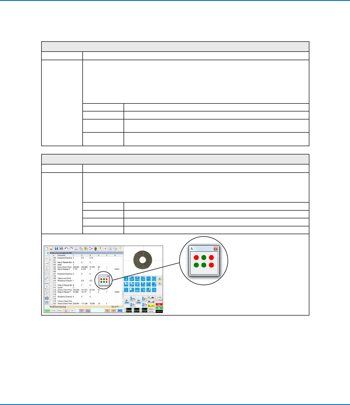
Used in tandem with the Positional Checking command to allow the camera to evaluate the dispensed dots
on an array against user-specified X and Y offsets. When a Positional Checking program runs, the Step &
Repeat Block command causes a window to open to show the status of each dot as a green (pass) or red
(fail) dot. Refer to “Positional Checking Example” on page27 for an example of how to use this command
in a program.
Parameter Description
Title A user-specified title for the window, with a maximum of 42 characters visible.
Columns (x) The number of columns in the X direction.
Rows (y) The number of rows in the Y direction.
Status window that opens during a
Positional Checking program; the
window title is user-specified (it is
titled “A” in this example)
AppendixA, Command Function Reference
(continued)