Nordson_EFD_OptiSure_Operating_Manual.pdf - 第56页
OptiSure Automated Optical Inspection 56 www.nordsonefd.com info@nordsonefd.com +1-401-431-7000 Sales and service of Nordson EFD dispensing systems are available worldwide. Using the Arr ow T ypes (continued) # Click Ste…
OptiSure Automated Optical Inspection
55www.nordsonefd.com info@nordsonefd.com +1-401-431-7000 Sales and service of Nordson EFD dispensing systems are available worldwide.
Using the Arrow Types (continued)
Mea. Width Example for Dispense Width Adjustment (continued)
To Create a Program for Dispense Width Adjustment
# Click Step Reference Image
1
>
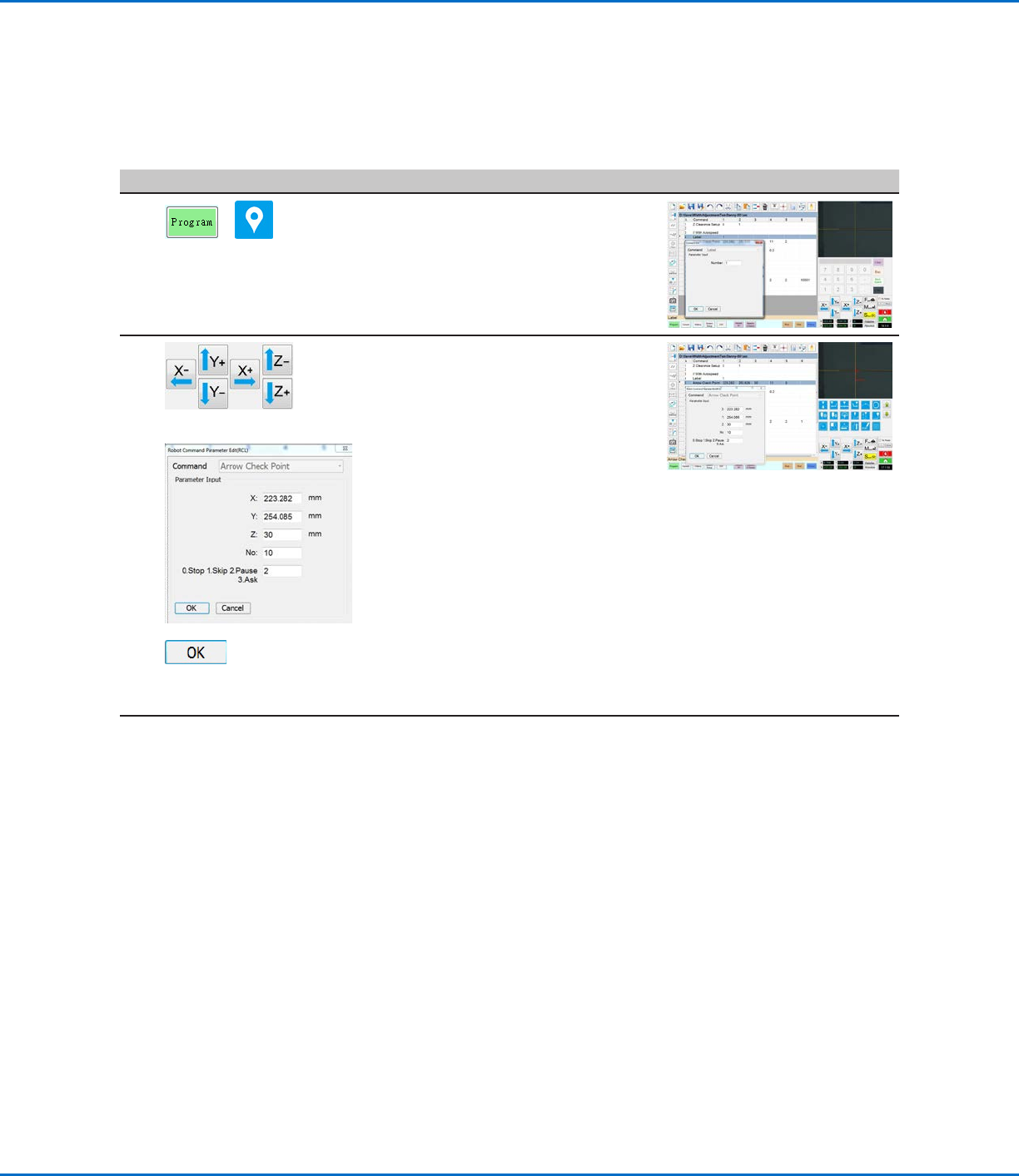
• Click the PROGRAM tab.
• Place the cursor in an empty
command address near the top of the
program and then click the LABEL
icon. In this example, the Label
Number is 1.
2
>
ARROW CHECK POINT >
>
• Jog the camera to the location on the
thinner line where you want the width
measurement to be checked during
subsequent dispenses.
• Under the LABEL command, insert
an ARROW CHECK POINT and enter
parameters as follows:
- Enter the number (No.) of the mark
image created for the thinner line in
the previous procedure (No. 10 in
this example).
- Select the action you want the
system to take if the measured line
section is above the Max value
or below the Min value specified
for the mark image (step 7 on
page54). Refer to “Arrow Check
Point” on page71 for details.
• Click OK.
Continued on next page
OptiSure Automated Optical Inspection
56 www.nordsonefd.com info@nordsonefd.com +1-401-431-7000 Sales and service of Nordson EFD dispensing systems are available worldwide.
Using the Arrow Types (continued)
# Click Step Reference Image
3
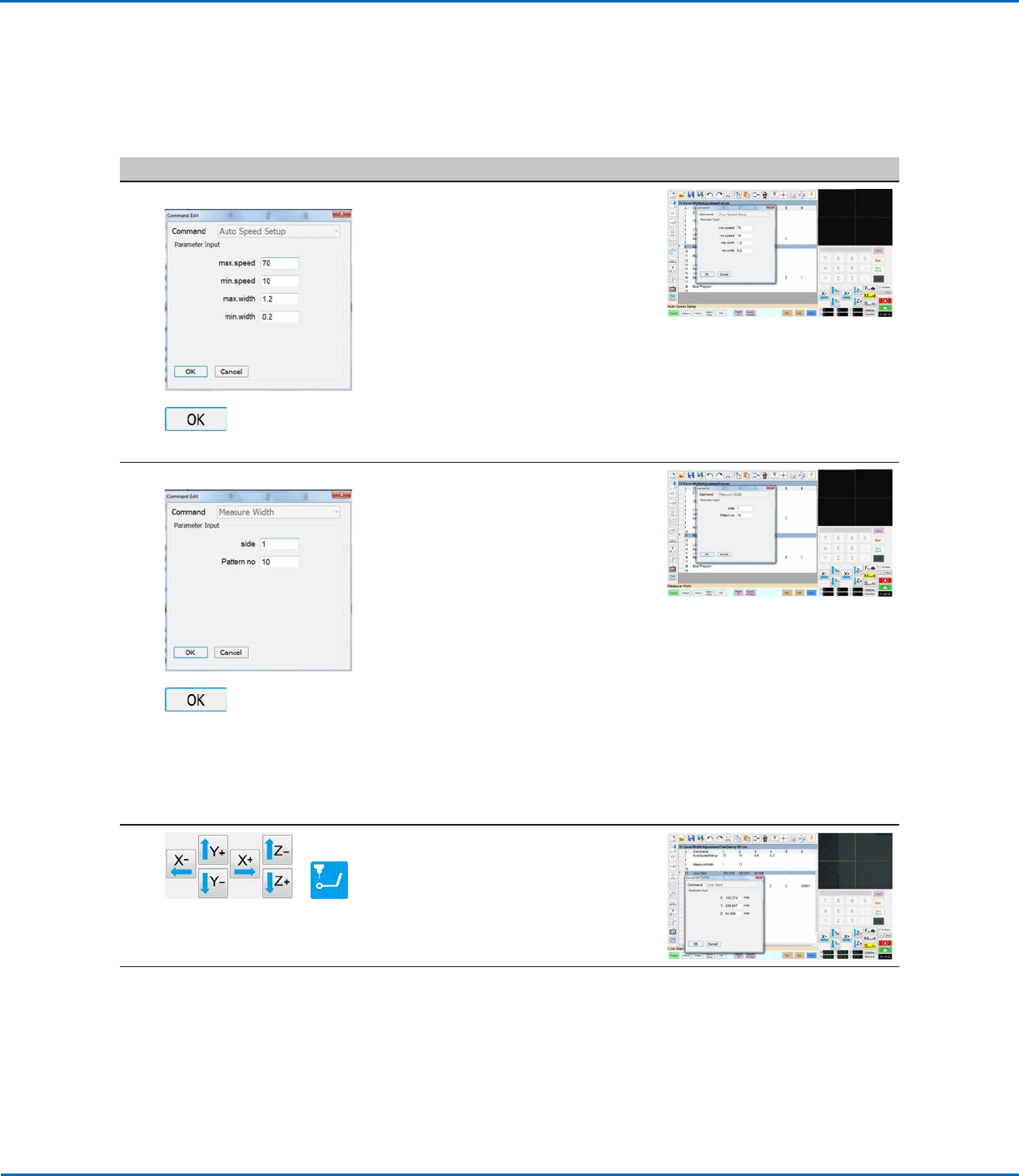
AUTO SPEED SETUP >
>
• Under the Arrow Check Point
command, insert an AUTO SPEED
SETUP command and enter
parameters as follows:
- Max. Speed: Enter the maximum
allowable robot line speed.
- Min. Speed: Enter the minimum
allowable robot line speed.
- Max. Width: Enter the maximum
allowable width of the line.
- Min. Width: Enter the minimum
allowable width of the line.
• Click OK.
4
MEASURE WIDTH >
>
• Under the Auto Speed Setup
command, insert a MEASURE WIDTH
command and enter parameters as
follows:
- Side: Enter a SIDE number to
specify the line to be measured
(refer to “Auto Speed” on
page72 for a diagram that
explains this parameter).
- Pattern No: Enter the number of the
mark image created for the line in
the previous procedure (No. 10 in
this example).
• Click OK.
NOTE: This command measures the
width of the dispensed line using the
coordinates specified in the Arrow
Check Point command.
5
>
• Jog the camera to the beginning of
the thinner line.
• In the next empty command address,
enter a LINE START command.
Continued on next page
Mea. Width Example for Dispense Width Adjustment (continued)
To Create a Program for Dispense Width Adjustment (continued)
OptiSure Automated Optical Inspection
57www.nordsonefd.com info@nordsonefd.com +1-401-431-7000 Sales and service of Nordson EFD dispensing systems are available worldwide.
Mea. Width Example for Dispense Width Adjustment (continued)
To Create a Program for Dispense Width Adjustment (continued)
Using the Arrow Types (continued)
# Click Step Reference Image
6
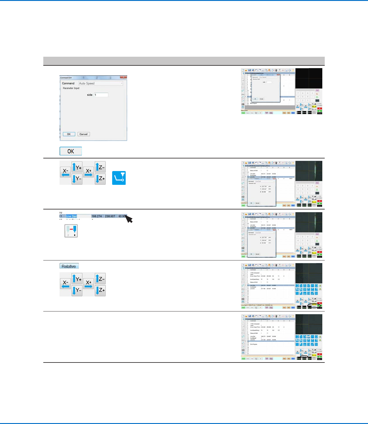
AUTO SPEED >
>
• Insert an AUTO SPEED command.
• For Side, enter the SIDE number
specified previously (in step 4, which
is Side 1 in this example).
• Click OK.
7
>
• Jog the camera to the end of the
thinner line.
• In the next empty command address,
enter a LINE END command.
8
>
• Highlight (select) the Line Start
command.
• Click Move to return the camera to
the beginning of the thinner line.
9
>
• Click RELATIVE.
• Jog the camera to the thicker line on
the workpiece template.
10 • Stop when you reach the new line,
then make a note of the relative Y
offset (13.087 in this example).
Continued on next page