Nordson_EFD_OptiSure_Operating_Manual.pdf - 第72页
OptiSure Automated Optical Inspection 72 www.nordsonefd.com info@nordsonefd.com +1-401-431-7000 Sales and service of Nordson EFD dispensing systems are available worldwide. Arrow Check Line Click Function Double-click ad…
OptiSure Automated Optical Inspection
71www.nordsonefd.com info@nordsonefd.com +1-401-431-7000 Sales and service of Nordson EFD dispensing systems are available worldwide.
AppendixA, Command Function Reference
This appendix provides detailed information for each setup and dispense command. Commands are in alphabetical
order.
The following rules apply to all commands:
• A command is in effect until it is superseded by another command.
• Command settings override system settings.
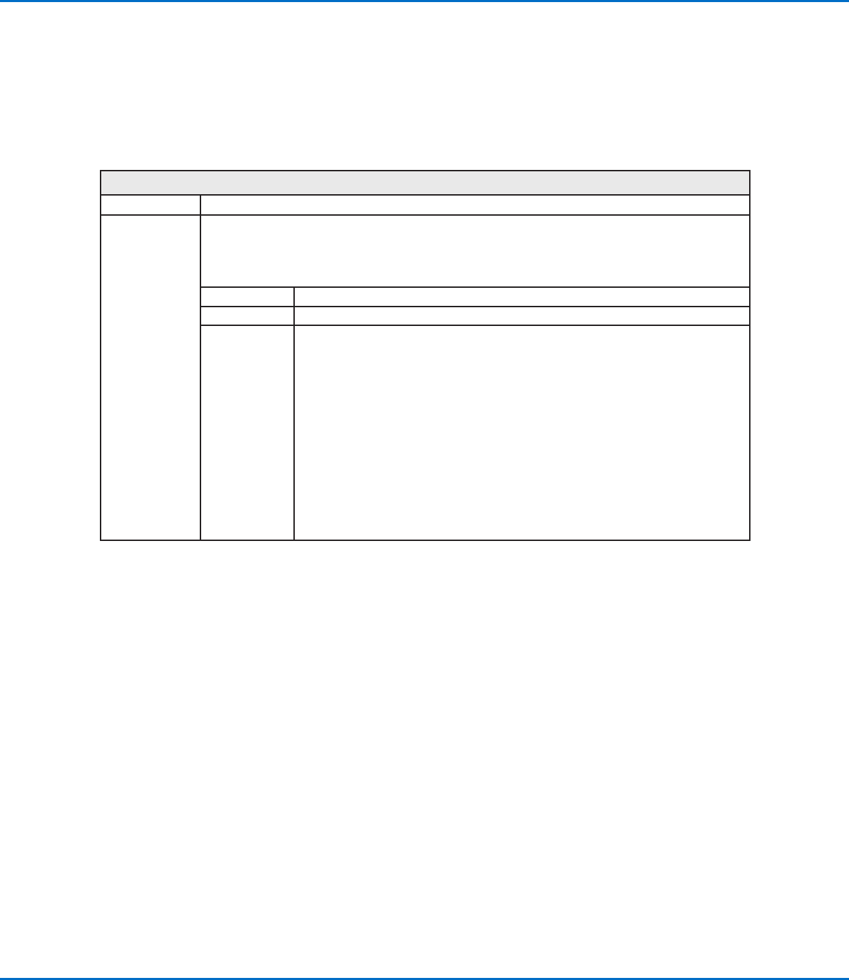
Arrow Check Point
Click Function
Double-click
address and
select from drop-
down menu
Used in tandem with the Mea. Width, Mea. Point to Line, and Positional Checking options of the
OptiSureAOI feature to check the width of a section of a dispensed line (between two specified points)
against a saved mark image that can specify Max and Min parameters for line width; if the width of a section
of dispensed line is not within the allowable range, the system takes the action specified by the Skip, Stop,
Pause, or Ask parameter.
Parameter Description
No. The number of the mark image saved for the line section.
0.Stop, 1.Skip,
2.Pause, 3.Ask
The action the system takes if a dispensed line section does not meet the parameters
specified for the saved mark image.
0.Stop The system stops running the program and displays an Arrow Check Fail
warning: Click OK to acknowledge the warning, then click HOME to move the
Zaxis to the Home position (0, 0, 0).
1.Skip The system skips the dispense and goes to the next command in the program.
2.Pause The system stops running the program and displays a “Waiting [Start] Button]”
box: Click START or CONTINUE to continue running the program; click STOP
and then HOME to stop the program and send the robot to the Home position
(0, 0, 0).
3.Ask The system stops running the program and displays a “Find Again, Find Next,
or Stop Find” box: Click FIND AGAIN to make the system check the point
again. Click FIND NEXT to go to the next command in the program. Click STOP
FIND to stop the program.
OptiSure Automated Optical Inspection
72 www.nordsonefd.com info@nordsonefd.com +1-401-431-7000 Sales and service of Nordson EFD dispensing systems are available worldwide.
Arrow Check Line
Click Function
Double-click
address and
select from drop-
down menu
Used in tandem with the Mea. Width option of the OptiSureAOI feature to check the width of a dispensed
line against a saved mark image; if the width of a dispensed line in not within the allowable range, the
system takes the action specified by the Skip, Stop, Pause, or Ask parameter.
Parameter Description
No. The number of the mark image saved for the line.
0.Stop, 1.Skip,
2.Pause, 3.Ask
The action the system takes if a dispensed line does not match the saved mark image.
0.Stop The system stops running the program and displays an Arrow Check Fail
warning: Click OK to acknowledge the warning, then click HOME to move the
Zaxis to the Home position (0, 0, 0).
1.Skip The system skips the dispense and goes to the next command in the program.
2.Pause The system stops running the program and displays a “Waiting [Start] Button]”
box: Click START or CONTINUE to continue running the program; click STOP
and then HOME to stop the program and send the robot to the Home position
(0, 0, 0).
3.Ask The system stops running the program and displays a “Find Again, Find Next,
or Stop Find” box: Click FIND AGAIN to make the system check the line again.
Click FIND NEXT to go to the next command in the program. Click STOP FIND
to stop the program.
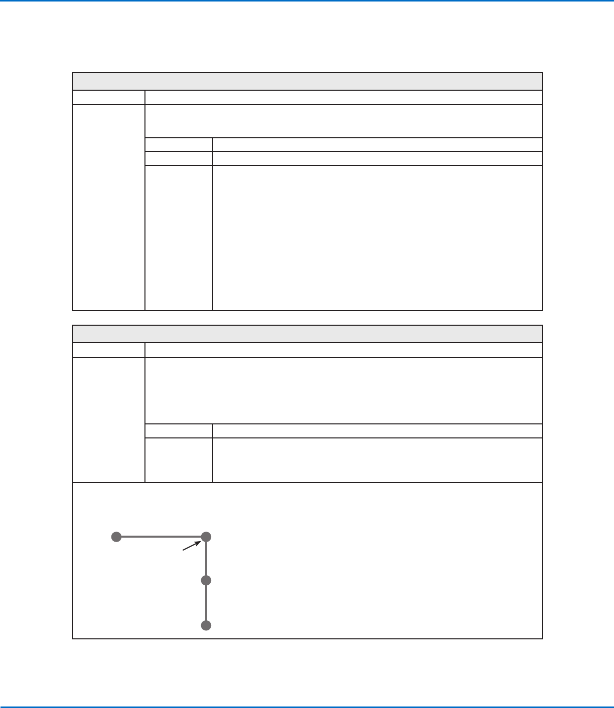
Auto Speed
Click Function
Double-click
address and
select from drop-
down menu
Used in tandem with the Mea. Width option of the OptiSureAOI feature, this command causes the system to
adjust the dispenser speed as needed to maintain the desired width of a dispensed line (based on the limits
defined by the Auto Speed Setup command). The line width to maintain is determined when the system
executes the Measure Width command, which identifies which line to measure based on its Side number.
NOTE: This command is present in the drop-down menu only when the main.bas file has been added to the
D:\ever_sr directory. The main.bas file is required for the dispense width adjustment feature.
Parameter Description
Side A number assigned to the dispensed line to check. See below for a diagram that explains
this parameter.
NOTE: This value must match the value defined for the Measure Width command, which
is also needed in the dispense program.
Line Start
Line End
Line Passing
Line Passing
}
Side 2
}
Side 1
AppendixA, Command Function Reference
(continued)
OptiSure Automated Optical Inspection
73www.nordsonefd.com info@nordsonefd.com +1-401-431-7000 Sales and service of Nordson EFD dispensing systems are available worldwide.
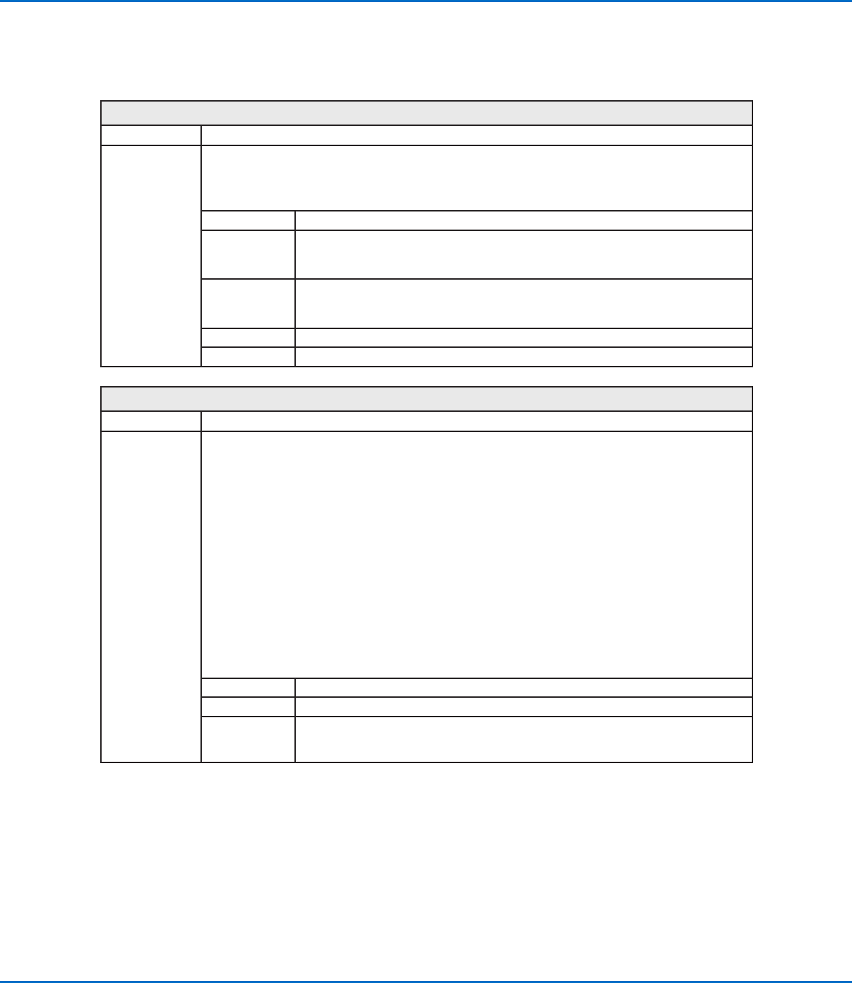
Auto Speed Setup
Click Function
Double-click
address and
select from drop-
down menu
Used in tandem with the Mea. Width option of the OptiSureAOI feature, this command defines the allowable
line speeds and widths for the Auto Speed command.
NOTE: This command is present in the drop-down menu only when the main.bas file has been added to the
D:\ever_sr directory. The main.bas file is required for the dispense width adjustment feature.
Parameter Description
Max. Speed The maximum line speed for the dispenser.
NOTE: This value cannot exceed the maximum line speed shown in the specifications
section of the robot manual.
Min. Speed The minimum line speed for the dispenser.
NOTE: This value cannot exceed the maximum line speed shown in the specifications
section of the robot manual.
Max. Width The maximum width allowed for the line.
Min. Width The minimum width allowed for the line.
Laser Profile
Click Function
Double-click
address and
select from drop-
down menu
Used in tandem with Laser Program to start or stop laser measurement. When turned ON, the system
uses the laser to measure and record the profile (displacement or thickness) of a fluid or a workpiece. The
resulting graph and measurements (data points) are exported as a *.JPEG and a *.CSV file, respectively.
When Laser Profile turns ON, the Laser Profile window opens to show the measurement data in real time.
In the Laser Profile window, you can enter threshold (tolerance) values and then enable them to cause the
system to check the laser measurements against the threshold values. If a measured value is outside the
threshold range, the system takes the action specified by the selected Stop, Skip, or Pause radio button in
the Laser Profile window. Refer to “To Check Laser Measurements Against Threshold Values” on page67
for details.
NOTES:
• This command applies to PROPlus/L and PRO/L systems only.
• Refer to “To Measure and Record the Profile of a Fluid or a Workpiece” on page63 for an example of
how to use this command in a program.
• The Laser Program command tells the system which laser measurement settings program to use. Refer to
“Laser Program” on page74 for details.
Setting Description
0 Off Turns Laser Profile OFF, stopping laser measurement.
1 On Turns Laser Profile ON, starting laser measurement and opening the Laser Profile
Window. The Laser Profile window can be closed and reopened during active
measurement.
AppendixA, Command Function Reference
(continued)