YG100R_Mainte_E.pdf - 第33页
2-3 2 Daily maintenance items 1 . 2 C h e c k i n g t h e n o z z l e s v i s u a l l y U s e e i t h e r o f t h e f o l l o w i n g t w o m e t h o d s t o c h e c k t h e n o z z l e t i p v i s u a l l y . n Re m o v…
2-2
2
Daily maintenance items
n
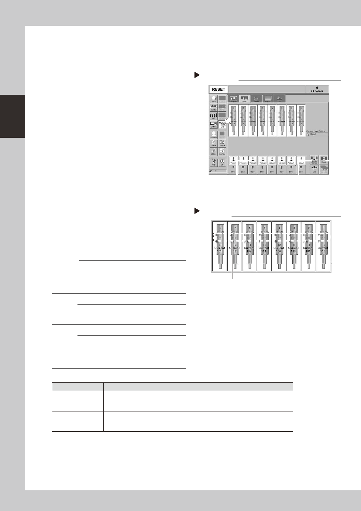
How to check for clogged nozzles (on the [Unit]-[Head] tab screen)
The term "clogged nozzle" used here indicates that material such as solder is adhering to the nozzle hole,
causing a rise in negative pressure even if no component is being picked up by the nozzle. This state might
cause problems such as component mounting errors. Check for clogged nozzles using the following procedure.
e
1
Attach the nozzle.
Press the emergency stop button and attach
Type 212A and 212F nozzles to all heads.
When the machine has a nozzle station,
press the [Nozzle Change] button to change
the nozzles.
54204-F9-00
2
Reset the numerical figure.
Open the [Unit] - [Head] tab screen. Then
press the [Reset] button on the lower right of
the screen to reset the pickup level values.
3
Generate negative pressure.
On the [Unit] - [Head] tab screen, and set
the [Vacuum] buttons for all heads to ON.
When this value starts rising, wait 5 to 10
seconds and set to OFF.
4
Check the vacuum levels.
Read the "Max" value shown in red on the
[Head] tab screen. If this value is 130 or less
then it is in normal range. If higher than 130,
then the nozzle hole might be dirty and
probably needs cleaning.
54205-F9-00
Reference
The above-mentioned value "130" is a general guide for
nozzle maintenance and the actual value to use may
differ slightly depending on operating conditions. Use
this "130" value for reference.
n
NOTE
The above example is for Type 212A, 212F nozzles so the
values shown will be different for other types of nozzles.
n
NOTE
If a correct value cannot be obtained after cleaning
even after performing steps 1 to 4, then the interior of
the spline shaft might be dirty. To check it, refer to the
table on the right.
n
Vacuum level in spline shaft air path
Nozzle Typical criteria
Type 213F nozzle
If the "Max" value is less than 100 while the nozzle is open, the vacuum level is normal.
If the "Max" value is more than 190 while the nozzle is sealed, the vacuum level is
normal.
Precision head
without nozzle
If the "Max" value is less than 80 while the nozzle is open, the vacuum level is normal.
If the "Max" value is more than 200 while the nozzle is sealed, the vacuum level is
normal.
* The vacuum level in the spline shaft air path might sometimes differ slightly depending on the air source and
operating conditions. Use the above criteria values for reference during maintenance.
Negative pressure generation
Step 1 to 3
[Nozzle Change] button[Vacuum] button [Reset] button
Negative pressure check
Step 4
Read "Max" values.
2-3
2
Daily maintenance items
1.2 Checking the nozzles visually
Use either of the following two methods to check the nozzle tip visually.
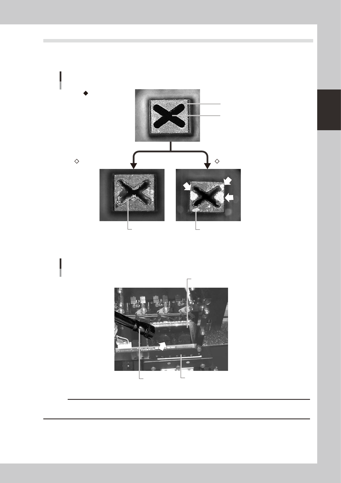
n
Remove the nozzle and check with a magnifying glass or similar tool.
Nozzle tip
Solder is adhering to nozzle hole
Solder is adhering to nozzle tip
Nozzle hole
Nozzle state
Normal condition
Clogged nozzle Shiny material on tip
53201-F9-00
n
Leave the nozzle installed and check with a hand mirror and flashlight.
Flashlight
Multi-vision camera
Hand mirror
Check with a hand mirror.
53202-F9-00
c
CAUTION
If the above check reveals a dirty or a clogged nozzle, promptly clean the nozzle by referring to sections 1.1 'Cleaning
"Type A" nozzles' and 1.2 "Cleaning Type F nozzles (YG100RA)" in Chapter 3.
2-4
2
Daily maintenance items
2. Checking the nozzle leaf springs
If nozzle leaf springs cannot hold a nozzle securely, this adversely affects pickup, recognition and mounting
operations. Periodically check the leaf springs for nozzle holding status.
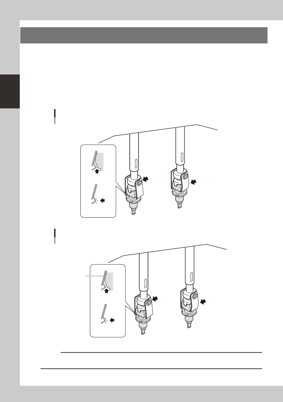
n
Leaf spring inspection points
Check the following points by removing the nozzle and reattaching it to the nozzle holder.
• The leaf spring has enough gripping force.
• There is no gap between the leaf springs and the nozzle.
• The leaf spring is not warped or deformed.
• The gripping part of the leaf spring is not frayed.
Checking the leaf spring condition
Standard head (head 2, 4, 6, 8)
There should be
no gap.
Leaf spring should
not be frayed.
Screw should
be tightened.
Leaf spring should not be
warped or deformed.
53203-F9-00
Added plate spring
(for increasing spring
force)
Checking the leaf spring condition
Precision heads (head 1, 3, 5, 7)
There should be
no gap.
Leaf spring should
not be frayed.
Screw should
be tightened.
Leaf spring should not be
warped or deformed.
53210-F9-00
c
CAUTION
If any of the above points is found to be a problem, remove the nozzle and replace the leaf springs as a pair, by
referring section 1, "Nozzle leaf springs" in Chapter 4.