YG100R_Mainte_E.pdf - 第63页
3-25 3 Periodic maintenance items 2 . 6 I n s p e c t i n g b a l l s c r e w s a n d l i n e a r g u i d e s o f e a c h a x i s I n s p e c t t h e b a l l s c r e w s a n d t h e l i n e a r g u i d e s o n t h e X , …
3-24
3
Periodic maintenance items
n
Coplanarity checker camera
When your machine is equipped with an optional coplanarity checker camera, check and clean the light
diffuser plate, half mirror and lens as explained below.
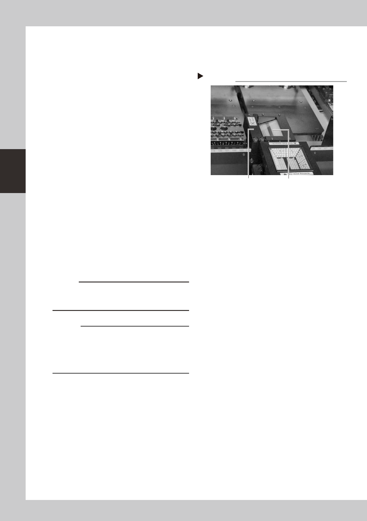
1
Check the camera for dust or
debris.
1. Check to see if dust or debris gets on the
light diffuser plate on top of the camera
unit.
2. When you look obliquely into the camera
unit, you will see a half mirror and lens
reflected on the half mirror. Check to see
if there is any dust or debris on these
parts.
53389-F9-00
2
Remove any dust or debris from
each part.
1. First, remove any dust from the light
diffuser plate with the blower brush.
If there are large debris particles on the
light diffuser plate, use tweezers to
remove them.
2. Next, remove any dust on the half mirror
and lens with the blower brush.
If there are large debris particles on the
lens, remove them with tweezers by
inserting them through the opening
located on the rear side of the camera
unit.
c
CAUTION
The light diffuser plate is a very thin sheet. Be careful not
to apply force or scratch the surface with hard objects
such as tweezers.
Reference
Depending on the machine specifications, there might
be no space allowing access to the lens from the rear
side of the camera unit. This makes it difficult to clean
the lens without disassembling the units around the
camera unit. In such cases, contact our local sales
office or sales representative for assistance.
3
Wipe the half mirror and lens.
Apply a few drops of lens cleaner to a
cotton swab (supplied with machine) and
wipe the half mirror and lens.
Checking for dust or debris
Step 1
Half mirror and lens (inner side) Light diffuser plate

3-25
3
Periodic maintenance items
2.6 Inspecting ball screws and linear guides of each axis
Inspect the ball screws and the linear guides on the X, Y and W axes. Check the following points.
Checkpoints
1. Any foreign matter adhering to the ball screws and linear guides?
Check if any fallen chips have adhered to the X and Y axis ball screws and/or X, Y and W axis linear guides.
2. Do the ball screws and linear guides have the correct amount of grease?
Check if grease has flowed off or splattered in the air failing to adhere. Also check if grease has discolored or hardened.
3. Any abnormal sounds from the ball screws?
Press the emergency stop button. Then check for any abnormal sounds while pressing the head assembly or conveyor
table by hand along the X-axis or Y-axis back and forth.
Countermeasures
1. Ball screws and linear guides may be damaged when chips and other material bite into them. If chips are adhering,
wipe them off along with the grease or remove with tweezers, etc.
2. Apply grease while referring section 2.2, "Cleaning and greasing the X, Y and W axes" explained in this chapter.
3. Consult your YAMAHA sales office or representative when abnormal sounds occur even after trying the
countermeasures in the above steps 1 and 2.
3-26
3
Periodic maintenance items
3. Six-month or one-year inspection
3.1 Cleaning and replacing the ejector filter
Although depending on the air supply conditions and operating time, ejectors should be inspected once every
6 months. Use an air blow gun to remove dust buildups when small. We recommend replacing the air filter if
heavy dust deposits are found.
1
Move the head assembly all the way
to the back end of the Y axis.
On the [Unit]-[Head] tab (or [conveyor] tab)
screen, press the [Axis] button to open the
"Move Axis" screen. Then move the head
assembly all the way to the rear of the Y axis
(rear of machine).
Reference
The ejector unit is located at the rear of the head
assembly. It is easier to inspect the ejector filters when
the head assembly is positioned to the front side of the
Y axis. (Inspect the ejector filters from the front of the
machine.)
e
2
Press the emergency stop button.
The machine should be in emergency stop
to ensure safety during work.
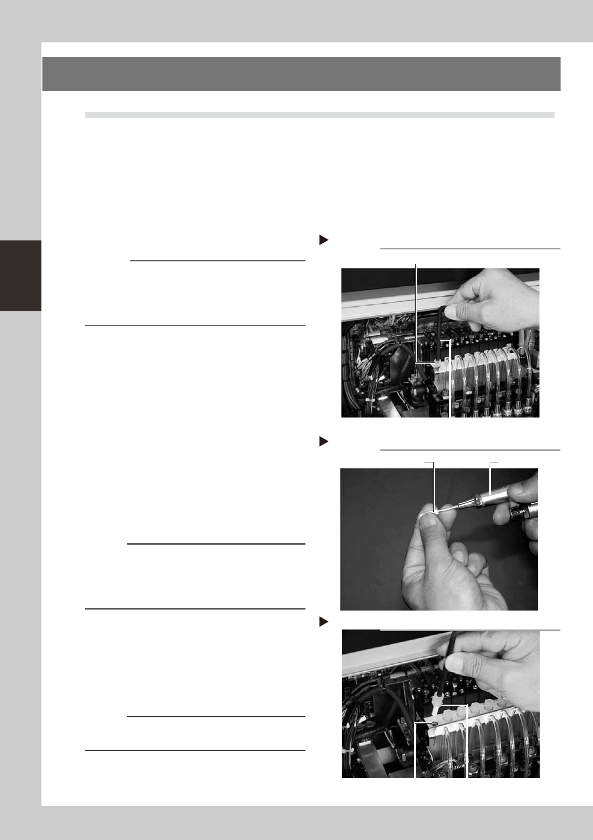
3
Remove the filter cap.
Loosen the filter cap with the M5 hex wrench
and remove it by hand.
53330-F9-10
4
Clean the filter.
Use tweezers to take the filter out of the
ejector. When there is only a little dust in the
filter, use an air blow gun to blow it away
and return the filter back to the original
position.
53331-F9-00
n
NOTE
If there are heavy dust deposits in the filter or the filter
has discolored, replace it with a new filter (K46-M8527-
C0X). As a general guide, filters should be replaced
once every 6 months, although this depends on the
actual operating time.
5
Reattach the filter cap.
1. Fit the filter into the filter cap and insert it
into the ejector.
2. Turn the filter cap to the right until it locks
and clicks.
53332-F9-10
c
CAUTION
Before inserting the filter, check that the O-ring is
placed in the ejector.
Removing the filter cap
Step 3
Hex wrench (M5)
Filter cap
Cleaning the filter
Step 4
Air blow gunFilter
Inserting the filter
Step 6
Filter fitted into the capO-ring