YG100R_Mainte_E.pdf - 第76页
4-7 4 How to replace consumable parts 4 . R e p l a c i n g t h e f e e d e r v a l v e s 1 T u r n o f f t h e m a c h i n e p o w e r s w i t c h . Q u i t t h e a p p l i c a t i o n s o f t w a r e ( V G O S ) a n d …
4-6
4
How to replace consumable parts
6
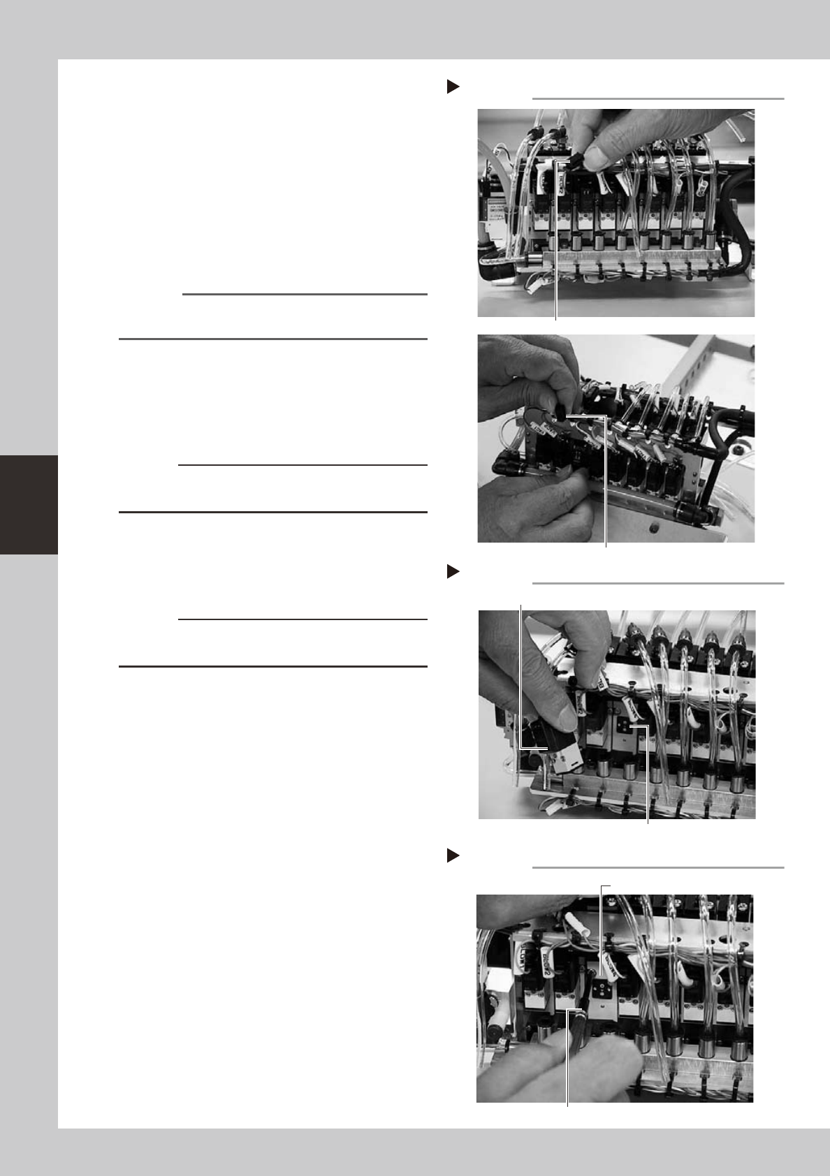
Unplug the connectors for the
ejector operate valve and blow
valve.
53410-F9-10
7
Remove the blow valve.
Use the precision Phillips screwdriver to
loosen the two screws securing the blow
valve and then remove the blow valve. You
will see the two screws securing the ejector
valve.
53411-F9-10
Reference
To replace an ejector valve, the blow valve attached
to that ejector valve must first be removed.
8
Remove the ejector valve.
Use the precision Phillips screwdriver to
loosen the two screws securing the ejector
valve and remove the ejector valve.
53413-F9-10
c
CAUTION
Be careful not to drop the gasket fitted to the backside
of the ejector valve.
9
Attach a new ejector valve.
Use the precision Phillips screwdriver to
tighten the two screws to secure the new
ejector valve.
c
CAUTION
Do not forget to fit the gasket in place. Use caution not
to fit the gasket inside-out or to pinch it.
0
Reassemble the valve unit in the
reverse order of the above
procedure.
Reconnect the air hoses and connectors
back to their original positions.
q
Check the operation.
After reassembling the valve unit, supply air
to the machine and turn on the machine
power switch. Then check that the vacuum
levels are normal, using the procedure
described in step 5 of section 3.2.2,
"Lubricating the slide section and checking
the negative pressure", in Chapter 3.
Step 7
Removing the blow valve
Ejector valve mounting screws
Blow valve
Step 8
Removing the ejector valve
Precision Phillips screwdriver
Ejector valve
Step 6
Unplugging the connectors
Blow valve connector
Ejector operate valve connector
4-7
4
How to replace consumable parts
4. Replacing the feeder valves
1
Turn off the machine power switch.
Quit the application software (VGOS) and
turn off the machine power switch by turning
it to the left.
2
Shut off the air supply.
Open the lower left cover on the front of the
machine and turn the air supply/shutoff
switch to the right to cut off the air supply.
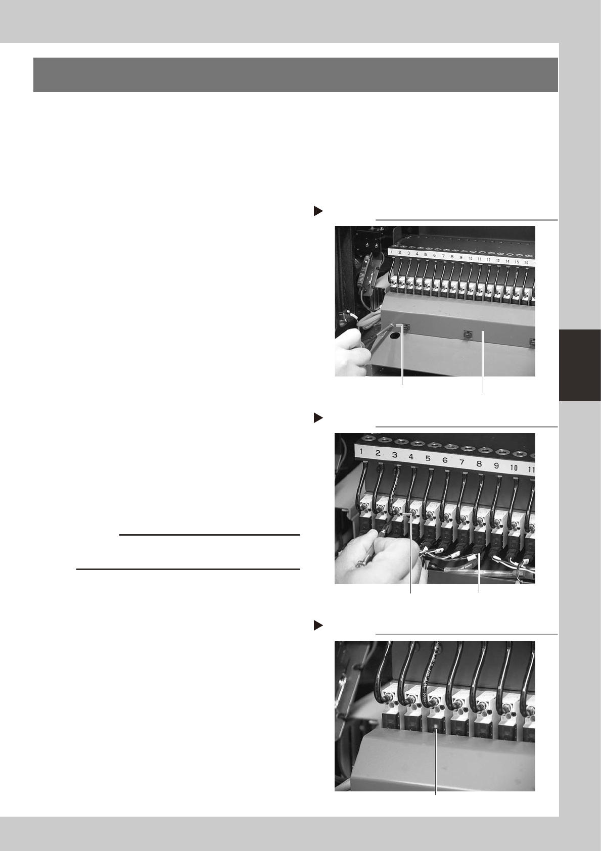
3
Remove the wire harness cover.
Use a Phillips screwdriver to loosen and
remove the screws that secure the wire
harness cover to the machine body.
53414-F9-00
4
Remove the feeder valve.
1. Detach the connector from the feeder
valve to be replaced.
2. Use a precision screwdriver to loosen the
two screws and remove the feeder valve.
53415-F9-00
5
Remove the air hose.
Remove the air hose for the feeder valve to
be replaced. Cutting the air hose makes it
easier to remove the air hose.
(New air hoses are included in the feeder
valve kit that comes with the machine.)
6
Attach a new feeder valve and the
wire harness cover.
Install the new feeder valve and wire
harness cover in the reverse order of steps 3
and 4.
c
CAUTION
Do not forget to fit the gasket in place. Use caution not
to fit the gasket inside-out or to pinch it.
7
Connect an air hose.
Connect a new air hose to the new feeder
valve.
8
Check the ejector operation.
1. Supply air to the machine and turn on
the machine power switch.
2. Install a feeder at the new feeder valve
position.
3. Open the [Unit]-[Feeder] tab screen and
turn the feeder on and off, to check the
feeder valve and LED operations.
53416-F9-00
Removing the wire harness cover
Step 3
Wire harness cover
Remove the screws
at both ends.
Removing the feeder valve
Step 4
Valve connector
Loosen these
two screws.
Checking the feeder valve operation
Step 8
LED lamp
4-8
4
How to replace consumable parts
5. Cleaning and replacing the conveyor belts
The conveyor belts are used in three conveyors: board carry-in conveyor, board clamp conveyor and board
carry-out conveyor.
The following explains the procedure for replacing the belts in the board clamp and carry-out conveyors.
When replacing the belt in the board carry-in conveyor, skip steps 4, 5 and 8.
1
Press the emergency stop button.
The machine must be in emergency stop to
ensure safety during work.
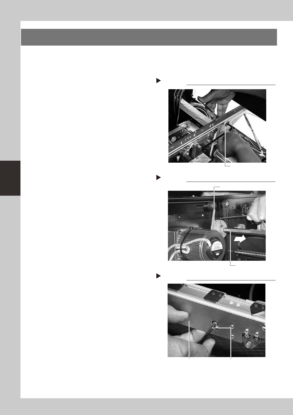
2
Slacken the belt.
Loosen the belt tensioner bolt with the M4
hex wrench and slide the bolt fully along the
elongate hole (in the direction of slackening
the belt).
53417-F9-10
3
Detach the belt.
Using the M3 hex wrench, loosen the bolt
securing the belt drive pulley and pull out
the shaft. Then detach the belt from the
pulley and take it out through the space
between the pulley and the shaft.
53418-F9-10
4
Remove the board clamp assembly.
Single type:
Using the M3 hex wrench, remove the two
bolts securing each board clamp assembly
and remove the board clamp assembly (one
assembly per belt).
Double type:
Using the M3 hex wrench, remove the two
bolts securing each board clamp assembly
and remove the board clamp assemblies
(two assemblies per belt).
53419-F9-10
Step 3
Removing the shaft
Shaft
Drive pulley
Loosening the belt tensioner bolt
Step 2
Tensioner bolt
Removing the board clamp assembly
Step 4
Board clamp assembly Board clamp assembly mounting bolt