YG100R_Mainte_E.pdf - 第67页
3-29 3 Periodic maintenance items 3 . 2 . 2 L u b r i c a t i n g t h e s l i d e s e c t i o n a n d c h e c k i n g t h e n e g a t i v e p r e s s u r e A f t e r c l e a n i n g t h e s p l i n e s h a f t s , l u b …

3-28
3
Periodic maintenance items
5
Blow air into the spline air path.
1. Insert the air tube into the fitting at the
top of the spline shaft to be cleaned.
2. Open the [Unit]-[Head] tab on the
operation display.
3. Press the [Blow] button on the operation
display to blow air into the spline air path
while placing cloth under the lower end
of the spline shaft.
54302-F9-00
6
Repeat the above procedure.
Disconnect the air tube and repeat step 4
and then step 5.
When the IPA flowing out from the spline
shaft becomes clean, blow air through the
spline air path as the last cleaning step. Use
the same procedure to clean all other
heads.
7
Reconnect the air tube to each
spline shaft and reattach all
nozzles.
Step 5
Blowing airinto spline shaft
[Blow] button
3-29
3
Periodic maintenance items
3.2.2 Lubricating the slide section and checking the negative pressure
After cleaning the spline shafts, lubricate the buffing parts (slide sections) and check the negative pressure
levels (vacuum levels).
1
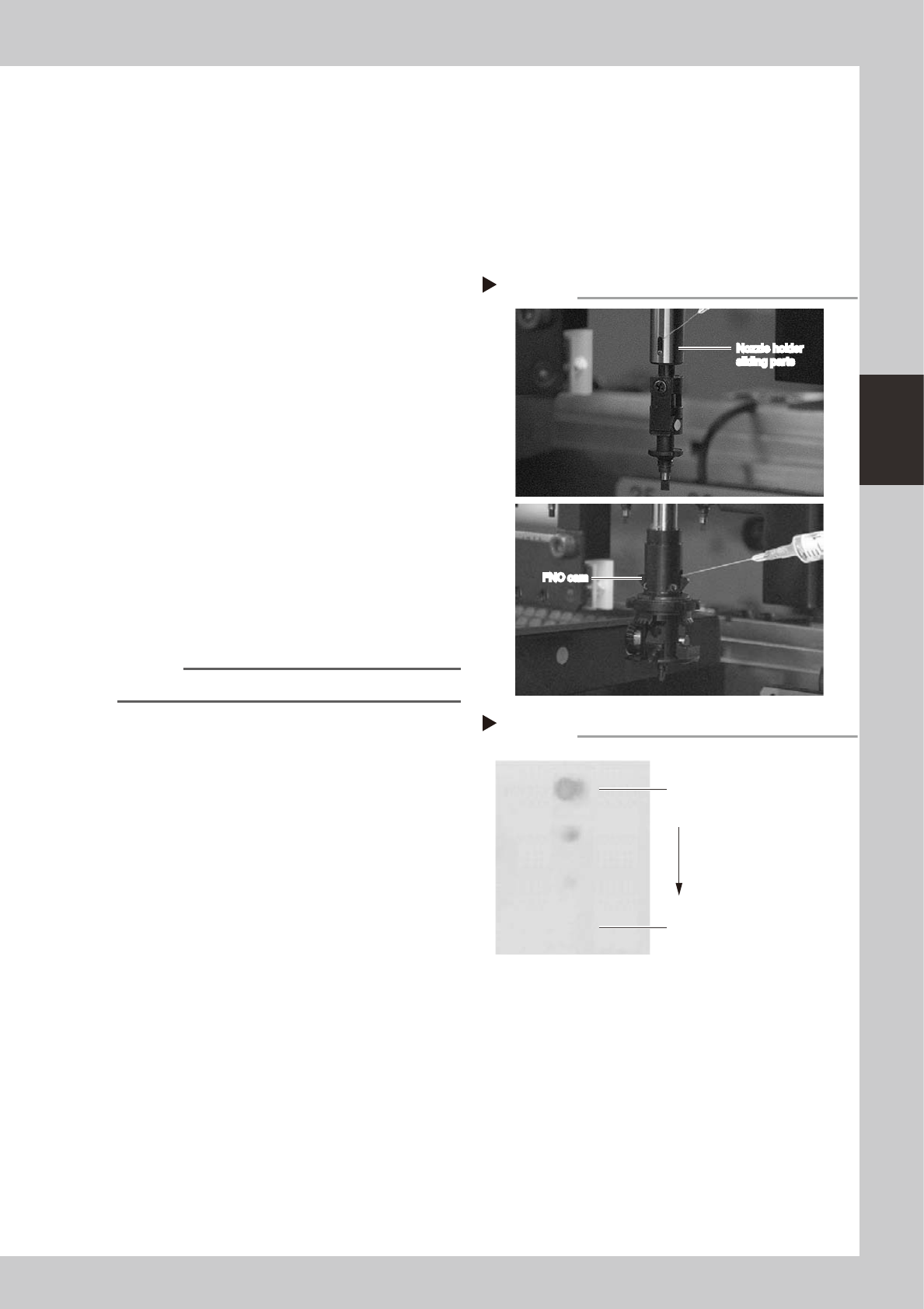
Lubricate the following parts.
Lubricating oil has been cleaned away by
IPA cleaning, so lubricate the following
parts.
Prepare the oil syringe applicator (KV8-
M8870-00X) filled with turbine oil (VG32).
1. Standard heads and YG100RB precision
heads: Apply one drop of oil at the
elongate holes at the joint between the
nozzle holder and the spline shaft. (2
locations for each spline shaft) After
applying the oil, move the nozzle holder
up and down several times.
2. FNC heads: Pull down the FNC index
holder, and you will see two small cams
on the FNC spline shaft. Apply one drop
of oil at each cam and then move it up
and down by hand several times.
53368-F9-00
2
Remove excess oil.
Using the air blow gun, blow air for about 5
seconds from the bottom of the spline shaft.
Then open the [Unit]-[Head] tab screen and
press the [Blow] button to blow air through
the spline shaft.
NOTE
A thin coat of oil is enough to lubricate the slide section.
3
Check that the oil was removed.
Blow air through the spline shaft again while
using commercially-available oil blotting
paper, and check for residual oil in the spline
shaft.
53397-F9-10
4
Install the FNC nozzle assemblies.
Reassemble all FNC nozzle assemblies
(YG100RA) by referring to section 1.2.4,
"Reassembling the FNC nozzle assembly" in
this chapter.
Step 2
Lubrication point
Nozzle holder
sliding parts
FNC cam
Nozzle holder
sliding parts
FNC cam
Step 4
Checking for residual oil
Oil blotting paper
Oil will appear after blowing air (first
time) for about 5 seconds from the
nozzle tip.
Repeat the air blow for about 5
seconds each from the nozzle tip
and from the attachment side.
This task is finished when oil no
longer appears.
3-30
3
Periodic maintenance items
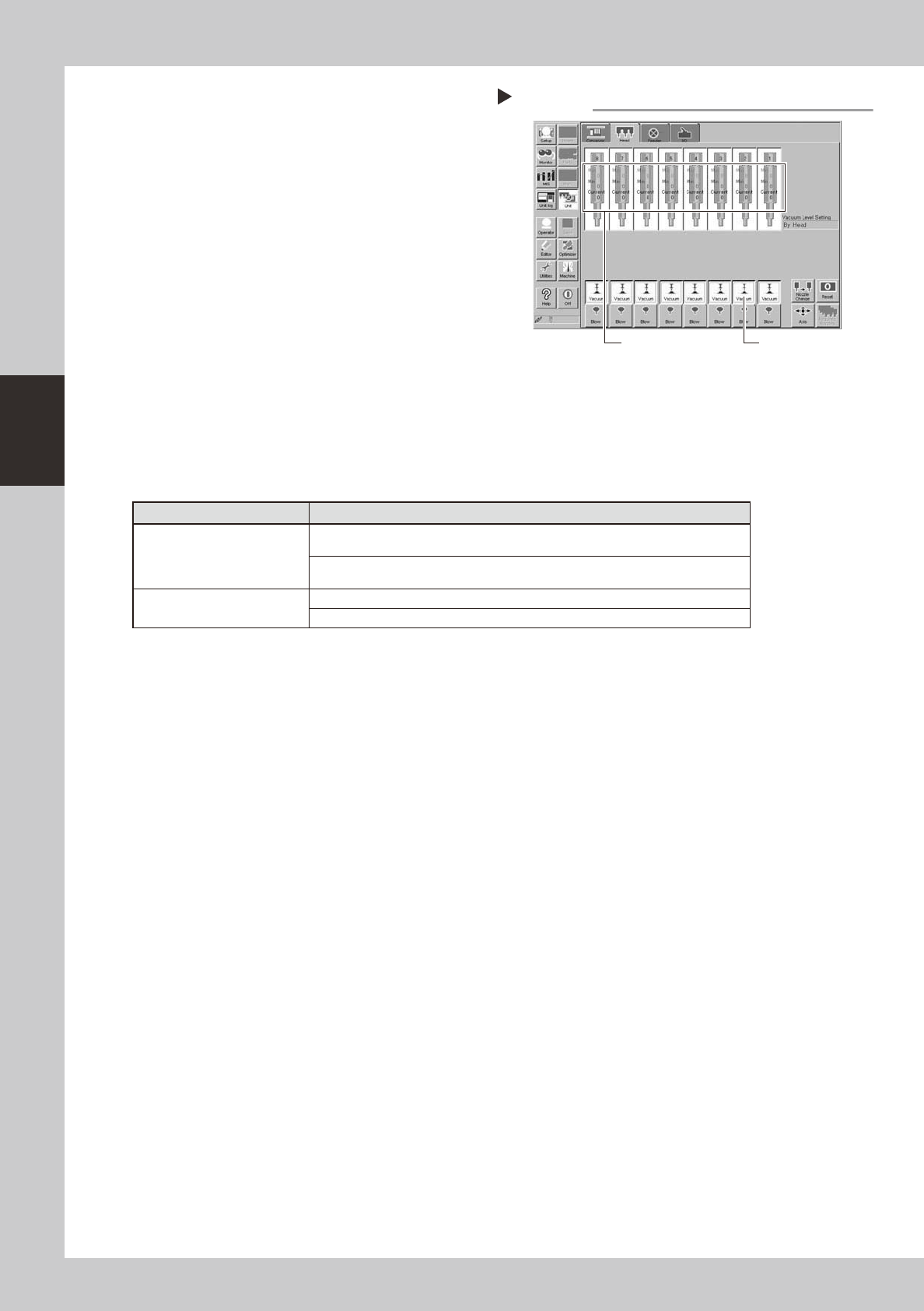
5
After assembly, check the vacuum
levels.
1. On the YG100RA, change the nozzle of
each FNC head to Type 213F, while leave
nozzles detached from the standard
heads. On the YG100RB, leave nozzles
detached from the precision heads.
2. Open the [Unit]-[Head] tab screen and
press the [Vacuum] button to generate a
negative pressure. Read the "Max" values
shown in red on the screen and
determine whether the vacuum levels
are appropriate by referring to the table
below.
54303-F9-10
6
Reattach the nozzles.
Attach the nozzles by hand back to the
standard heads or to the precision heads of
the YG100RB.
n
Vacuum level in spline shaft air path
Nozzle Typical criteria
FNC head with Type 213F
nozzle
If the "Max" value is less than 100 while the nozzle is open, the vacuum level is
normal.
If the "Max" value is more than 170 while the nozzle is sealed, the vacuum level is
normal.
Standard head and precision
head without nozzle
If the "Max" value is less than 80 while open, the vacuum level is normal.
If the "Max" value is more than 180 while sealed, the vacuum level is normal.
* The vacuum level in the spline shaft air path might sometimes differ slightly depending on the air source and
operating conditions. Use the above criteria values for reference during maintenance.
Checking the vacuum level
Step 6
[Vacuum] button
Read "Max" values.