YG100R_Mainte_E.pdf - 第65页
3-27 3 Periodic maintenance items 3 . 2 C l e a n i n g a n d l u b r i c a t i n g t h e i n s i d e o f t h e s p l i n e s h a f t A l t h o u g h d e p e n d i n g o n t h e a i r s u p p l y c o n d i t i o n s a n …
3-26
3
Periodic maintenance items
3. Six-month or one-year inspection
3.1 Cleaning and replacing the ejector filter
Although depending on the air supply conditions and operating time, ejectors should be inspected once every
6 months. Use an air blow gun to remove dust buildups when small. We recommend replacing the air filter if
heavy dust deposits are found.
1
Move the head assembly all the way
to the back end of the Y axis.
On the [Unit]-[Head] tab (or [conveyor] tab)
screen, press the [Axis] button to open the
"Move Axis" screen. Then move the head
assembly all the way to the rear of the Y axis
(rear of machine).
Reference
The ejector unit is located at the rear of the head
assembly. It is easier to inspect the ejector filters when
the head assembly is positioned to the front side of the
Y axis. (Inspect the ejector filters from the front of the
machine.)
e
2
Press the emergency stop button.
The machine should be in emergency stop
to ensure safety during work.
3
Remove the filter cap.
Loosen the filter cap with the M5 hex wrench
and remove it by hand.
53330-F9-10
4
Clean the filter.
Use tweezers to take the filter out of the
ejector. When there is only a little dust in the
filter, use an air blow gun to blow it away
and return the filter back to the original
position.
53331-F9-00
n
NOTE
If there are heavy dust deposits in the filter or the filter
has discolored, replace it with a new filter (K46-M8527-
C0X). As a general guide, filters should be replaced
once every 6 months, although this depends on the
actual operating time.
5
Reattach the filter cap.
1. Fit the filter into the filter cap and insert it
into the ejector.
2. Turn the filter cap to the right until it locks
and clicks.
53332-F9-10
c
CAUTION
Before inserting the filter, check that the O-ring is
placed in the ejector.
Removing the filter cap
Step 3
Hex wrench (M5)
Filter cap
Cleaning the filter
Step 4
Air blow gunFilter
Inserting the filter
Step 6
Filter fitted into the capO-ring
3-27
3
Periodic maintenance items
3.2 Cleaning and lubricating the inside of the spline shaft
Although depending on the air supply conditions and operating time, dust or grime adheres to the air path of
the spline shaft and may cause component pickup or mounting errors. The inside of the spline shaft should be
cleaned once every 6 months.
3.2.1 Cleaning the inside of the spline shaft
1
Remove the nozzles from all heads.
After making sure that the emergency stop
button is pressed, remove all nozzles.
On standard heads and YG100RB precision
heads (roller lock clamp heads): Remove
the nozzles by hand.
On YG100RA FNC heads: Remove the FNC
nozzle assemblies by referring to section
1.2.1, "Removing FNC nozzle assembly"
earlier in this chapter.
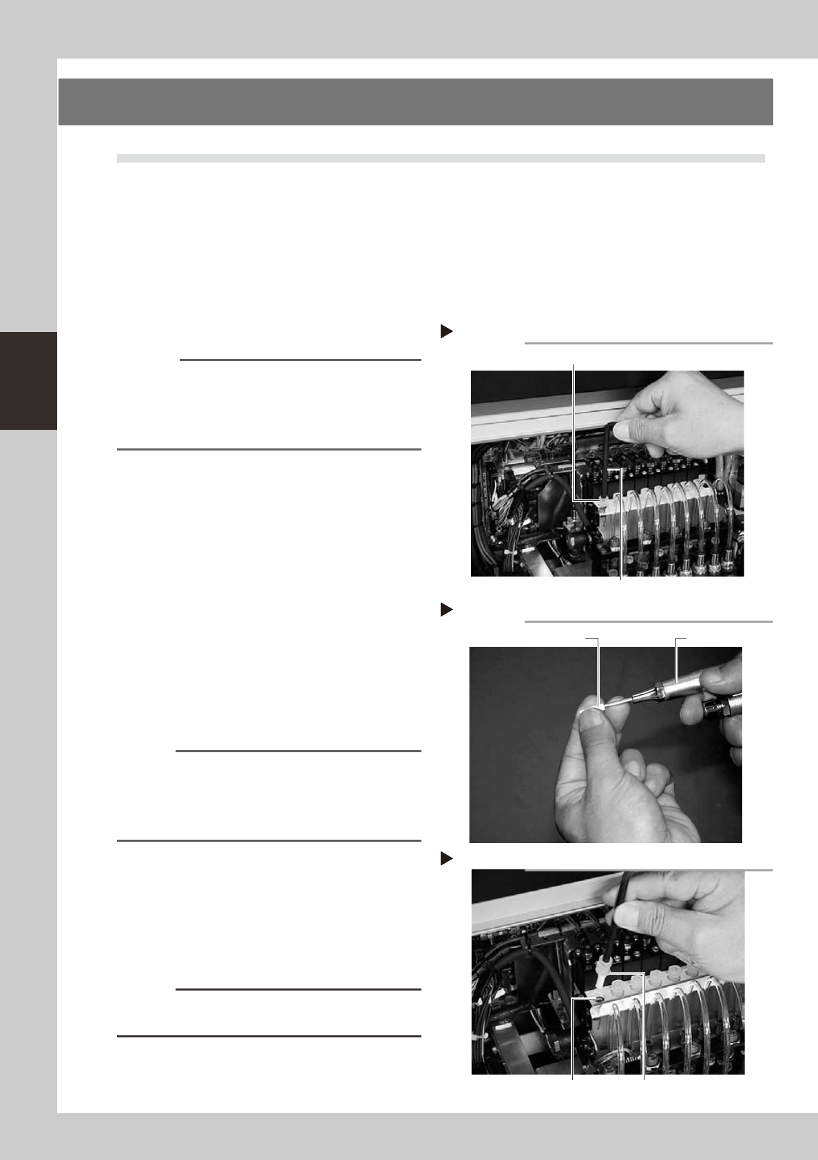
2
Disconnect the air tube from each
spline shaft.
As shown in the photo, disconnect the air
tube inserted into the fitting at the top of
each spline shaft.
53390-F9-10
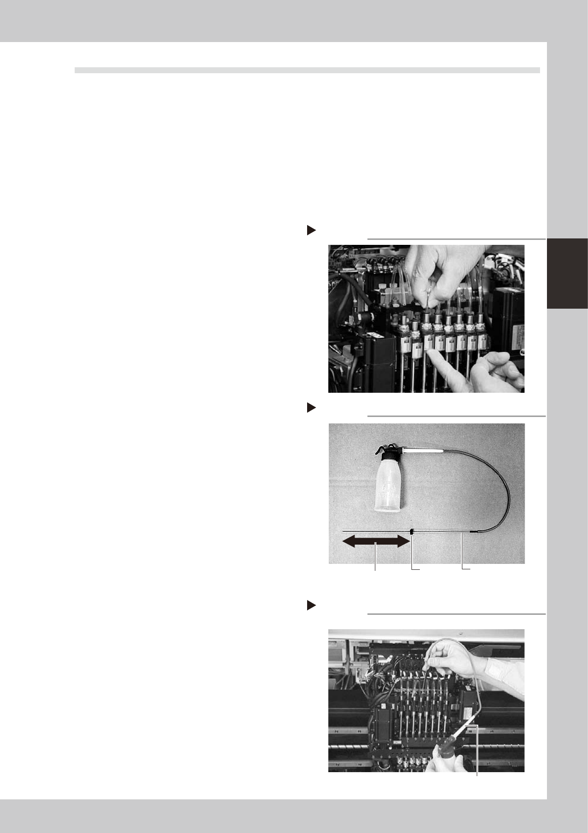
3
Prepare the cleaning kit (KV8-
M8860-00X).
1. Pour IPA (isopropyl alcohol) into the
container of the cleaning kit. (Never pour
other solvent into the container.)
2. Slide the stopper on the nozzle tube of
the cleaning kit so it is positioned 185 to
200mm away from the nozzle tip.
3. Place a paper cup or tray under the
spline shaft to be cleaned. (This prevents
IPA from flowing out downwards in step
4.)
53362-F9-00
4
Clean the inside of each spline
shaft.
1. Insert the nozzle of the cleaning kit into
the spline shaft until the stopper on the
nozzle tube makes contact with the top
of the spline shaft.
2. Pour alcohol (IPA) into the spline shaft air
path to clean away dust and grime.
53363-F9-00
Disconnecting the air tubes
Step 2
Cleaning tool
Step 3
Stopper
Nozzle
Set the stopper at a position
185 to 200mm away from the nozzle tip.
Cleaning the spline shaft
Step 4
Cleaning tool
3-28
3
Periodic maintenance items
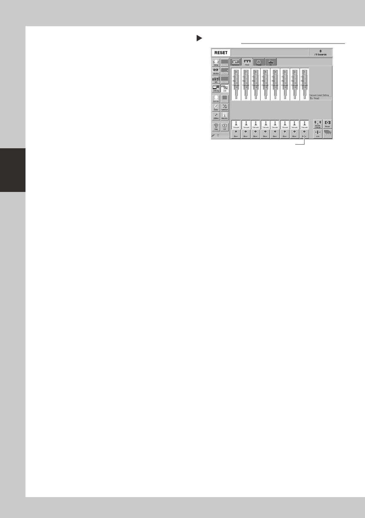
5
Blow air into the spline air path.
1. Insert the air tube into the fitting at the
top of the spline shaft to be cleaned.
2. Open the [Unit]-[Head] tab on the
operation display.
3. Press the [Blow] button on the operation
display to blow air into the spline air path
while placing cloth under the lower end
of the spline shaft.
54302-F9-00
6
Repeat the above procedure.
Disconnect the air tube and repeat step 4
and then step 5.
When the IPA flowing out from the spline
shaft becomes clean, blow air through the
spline air path as the last cleaning step. Use
the same procedure to clean all other
heads.
7
Reconnect the air tube to each
spline shaft and reattach all
nozzles.
Step 5
Blowing airinto spline shaft
[Blow] button