YG100R_Mainte_E.pdf - 第72页
4-3 4 How to replace consumable parts 2 . R e p l a c i n g t h e a i r j o i n t e 1 Pr e s s t h e e m e r g e n c y s t o p b u t t o n . T h e m a c h i n e m u s t b e i n e m e r g e n c y s t o p t o e n s u r e s…
4-2
4
How to replace consumable parts
1.2 Replacing the nozzle leaf springs of precision heads (YG100RB)
e
1
Press the emergency stop button.
The machine must be in emergency stop to
ensure safety during work.
2
Remove the nozzle.
Remove the nozzle attached to the leaf
springs to be replaced, by pulling it
downwards by hand.
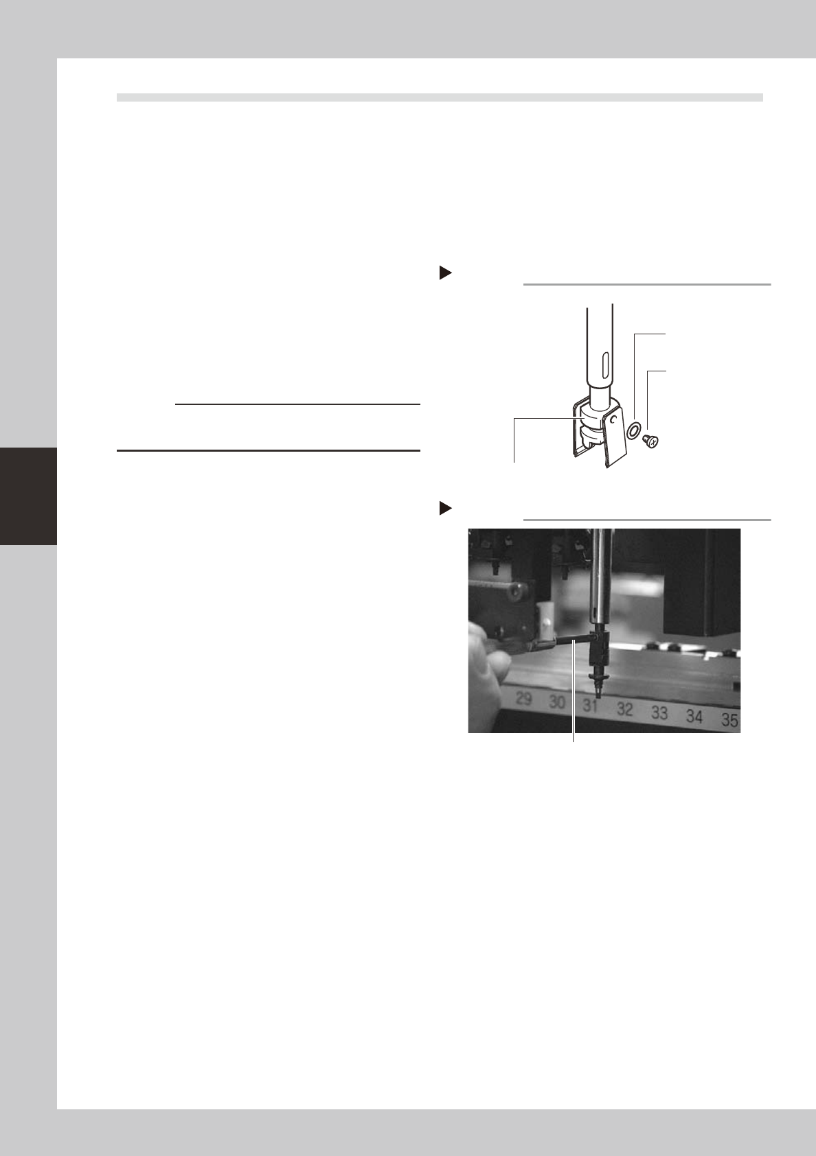
3
Remove the leaf springs.
Use a Phillips precision screwdriver to loosen
the screws securing the leaf springs and
remove the leaf springs from the nozzle arm
assembly, along with the plate springs used
for increasing the spring force.
53420-F9-00
c
CAUTION
When removing the leaf springs, the nozzle arms will
also come off. Be careful not to drop them.
4
Attach new leaf springs.
While pressing the new leaf spring and plate
spring up against the nozzle arm assembly,
tighten the screw with the precision
screwdriver. At this point, do not forget to fit
the washer.
53402-F9-00
5
Reattach the nozzle.
6
Check that the nozzle is held
securely.
1. Check that there is no gap between the
leaf springs and nozzle.
2. Attempt detaching and attaching the
nozzle several times to check that there
is no looseness.
Removing leaf springs
Step 3
Nozzle leaf spring
mounting washer
Nozzle holder
Nozzle leaf spring
mounting screw
Attaching leaf springs
Step 4
Precision Phillips screwdriver
4-3
4
How to replace consumable parts
2. Replacing the air joint
e
1
Press the emergency stop button.
The machine must be in emergency stop to
ensure safety during work.
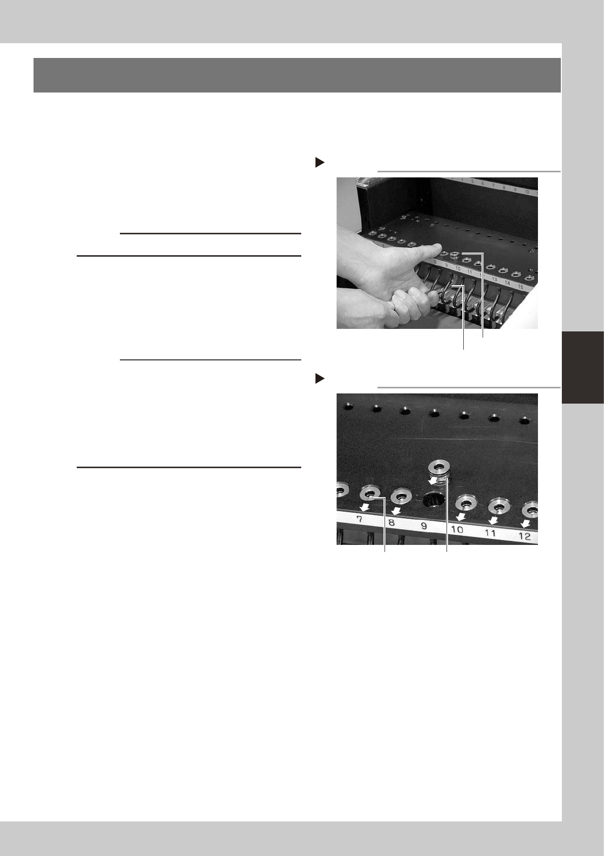
2
Remove the defective air joint.
Insert an M8 hex wrench at the bottom of
the air joint and push it up, then take the air
joint out.
53403-F9-00
c
CAUTION
Be careful not to damage the air hoses.
3
Install a new air joint.
While holding the air joint so the mark
(notch) faces the front side of the machine,
insert it into position from the top of the
feeder plate.
53404-F9-00
c
CAUTION
• Make sure that the mark (notch) faces the front side
of the machine. If the air joint is inserted without
aligning the mark orientation, dust or debris may
penetrate into the air hose.
• Fully insert each air joint into position so that its
surface is lower than the feeder plate surface. Air
joints will slightly rise over time. Reinsert them into
position.
4
Check the operation.
1. Install a feeder at the new air joint
position.
2. Open the [Unit]-[Feeder] tab screen and
check the feeder on/off operation.
Removing the air joint
Step 2
Air joint
Hex wrench
Installing an air joint
Step 3
Mark orientation
Concave mark
4-4
4
How to replace consumable parts
3. Replacing the ejector valves
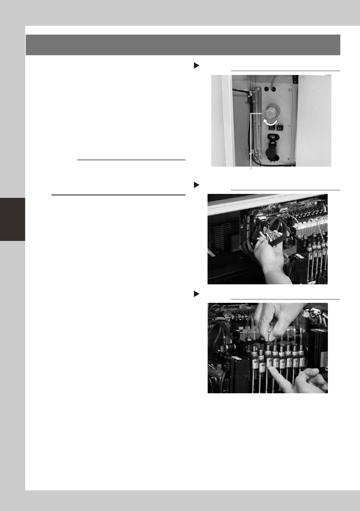
1
Shut off the air supply and turn off
the machine.
Turn the air supply/shutoff switch to the right
to cut off the air supply, quit the software,
and turn off the machine power switch.
53405-F9-10
2
Unplug the valve unit connectors.
Unplug two wire harness connectors (CN9,
CN11) that connect the valve unit to the I/O
board on the head assembly.
53407-F9-10
c
CAUTION
Thin harness wires are connected to the connector
housing. Be careful not to break those wires.
Unplug the connector by holding the connector
housing itself. Do not pull on the wire harness.
3
Disconnect the air tubes.
As shown in the photo, disconnect the air
tube inserted into the fitting at the top of
each spline shaft.
53406-F9-10
Step 1
Shutting off the air supply
Air supply/shutoff switch
Step 3
Disconnecting the air tubes
Step 2
Unplugging the valve unit connectors