YG100R_Mainte_E.pdf - 第52页
3-14 3 Periodic maintenance items 7 W i p e a w ay e x c e s s o i l . W i p e a w a y e x c e s s o i l w i t h a l i n t - f r e e c l e a n i n g c l o t h o r p a p e r t o w e l . 8 B l o w o f f e xc e s s o i l r …
3-13
3
Periodic maintenance items
2. Monthly or bimonthly inspection
This section explains how to clean and lubricate a nozzle holder after inspection.
2.1 Cleaning and lubricating a nozzle holder
If the nozzle holder spring-action is poor, this adversely affects all operations of component pickup, recognition
and mounting. Periodically (once every two months) clean the nozzle holder with alcohol (IPA or ethanol) and
lubricate it with turbine oil to maintain smooth movement.
e
1
Press the emergency stop button.
The machine must be in emergency stop to
ensure safety during work.
2
Remove the nozzles and lower the
heads.
Remove the nozzles attached to the nozzle
holders to be cleaned, and then lower the
heads by pressing the [Head] button on the
[Unit]-[Head] tab screen.
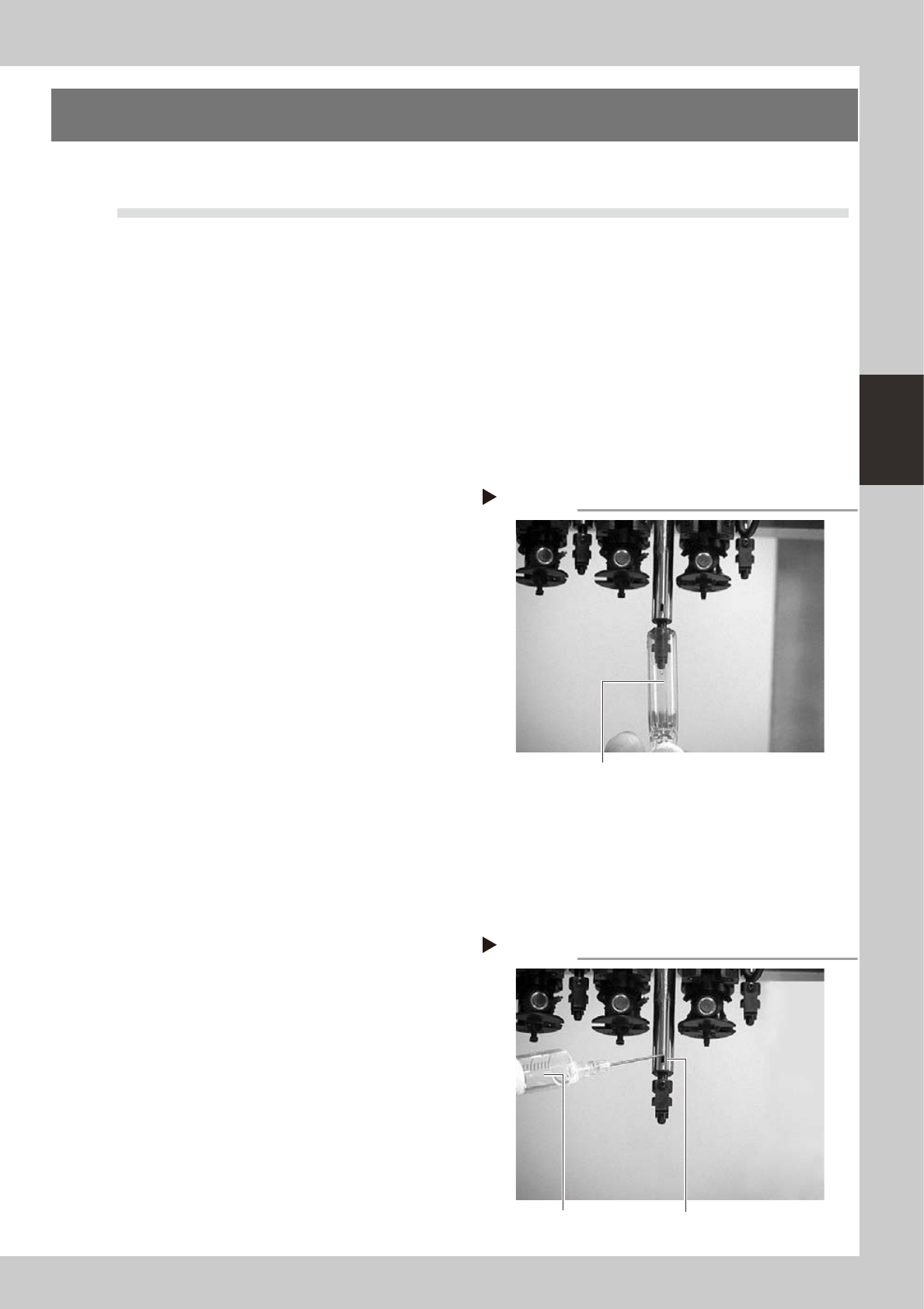
3
Clean the nozzle holder by
immersing it in alcohol.
1. Place a cloth or absorbent paper under
the head.
2. Prepare a small container of about
10mm diameter deep enough to hold
the entire nozzle holder. Then pour this
container about 80% full of alcohol.
3. Bring this alcohol container up against
the nozzle shaft so the entire nozzle
holder is immersed in alcohol for several
seconds.
4. Remove the alcohol container and push
up on the nozzle holder with your finger
several times.
53314-F9-00
4
Immerse the nozzle holder in
alcohol again.
Repeat steps 3 and 4 until the spring-action
becomes smooth.
5
Use air blow to remove foreign
matter.
Insert an air blow gun into the air joint
section and blow air while holding a
cleaning cloth or paper towel against the
lower end of the head.
6
Lubricate the slide section and
check the movement.
Apply turbine oil to the buffing section (slide
section) and push up the nozzle holder by
hand several times to check that it moves
up and down smoothly.
53315-F9-00
Cleaning the nozzle holder
Step 3
Container holding alcohol
Lubricating the nozzle holder
Step 6
Lubricate here.
Nozzle holder
lubricating syringe
3-14
3
Periodic maintenance items
7
Wipe away excess oil.
Wipe away excess oil with a lint-free
cleaning cloth or paper towel.
8
Blow off excess oil remaining in the
nozzle holder.
As in step 5, insert the air blow gun into the
air joint section and blow air through the
spline shaft while holding a cleaning cloth or
paper towel against the lower end of the
head.
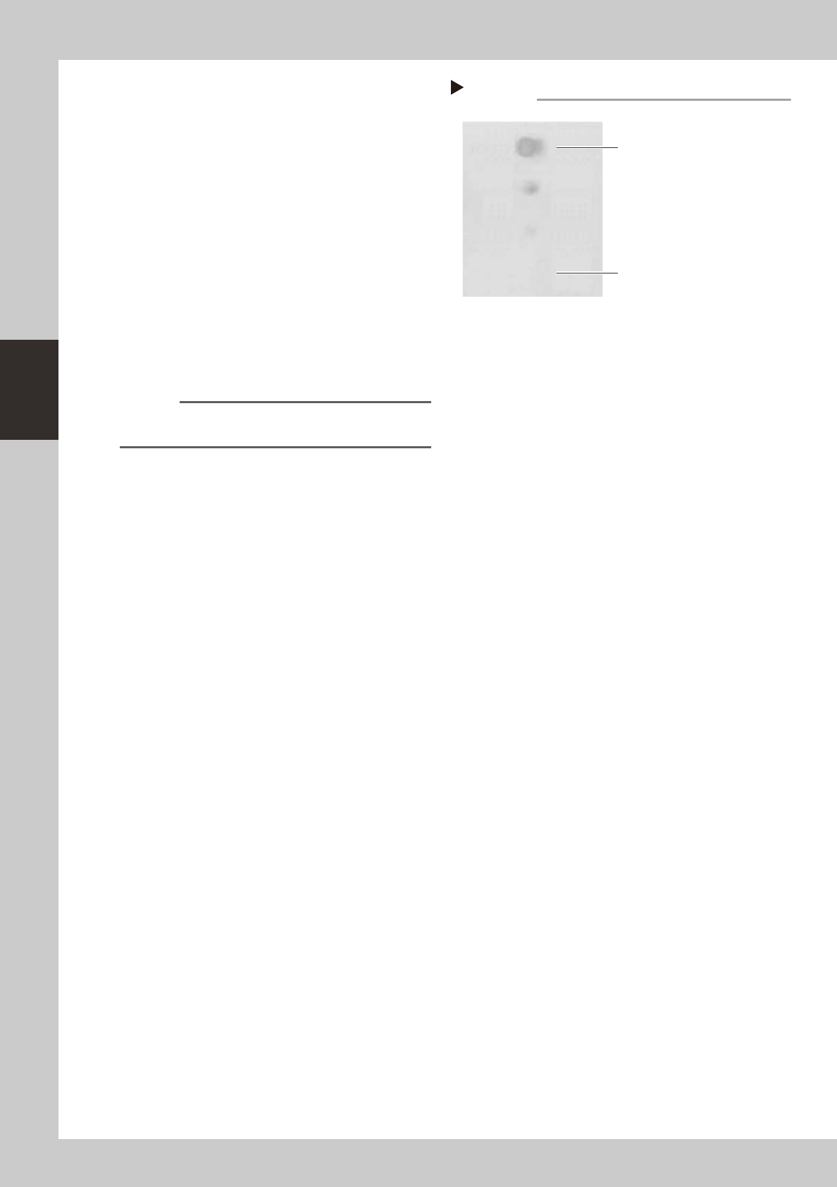
9
Check that the oil was removed.
Blow air through the spline shaft again while
using commercially-available oil blotting
paper, and check for residual oil in the
nozzle holder.
53396-F9-00
n
NOTE
Performing step 8 is usually sufficient to remove residual
oil. However, if oil still remains then blow air once again.
0
Reinstall the nozzle.
Reinstall the nozzle back onto the head or
the nozlle station (option).
Step 9
Checking for residual oil
Oil blotting paper
Repeat the air blow until oil no
longer appears.
Oil may appear after blowing air.
3-15
3
Periodic maintenance items
2.2 Cleaning and greasing the X, Y and W axes
To clean and grease the ball screws and linear guides of the X, Y and W axes, follow the steps below. Prepare a
grease gun and specified grease (NSL).
c
CAUTION
When handling grease or lubricant, read and follow the precautions listed in section 2.2.2, "Lubricating tools and
grease" in Chapter 1.
2.2.1 Cleaning and greasing the X, Y and W axis ball screws
e
1
Press the emergency stop button.
The machine must be in emergency stop to
ensure safety during work.
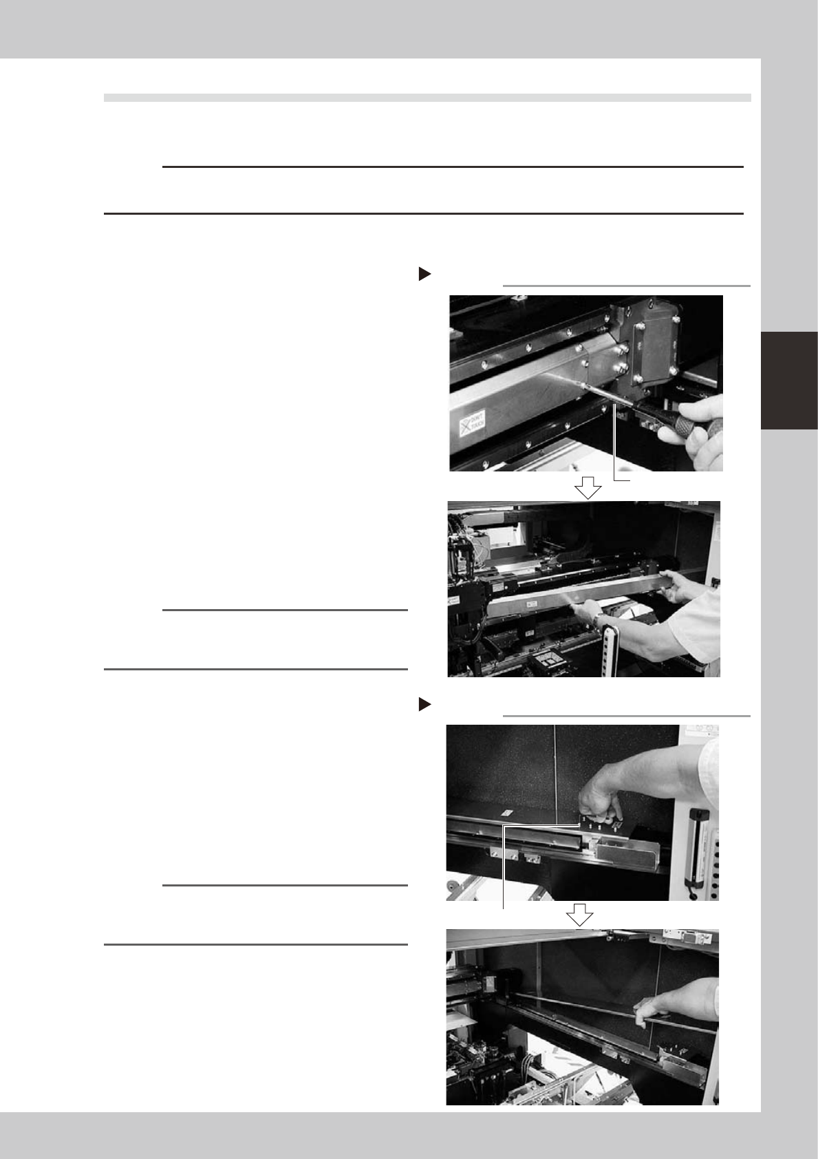
2
Remove the ball screw covers.
Remove the X-axis and Y-axis ball screw
covers used for preventing grease
spattering.
X-axis
1. Use a Phillips screwdriver to remove the
screws securing the left side of the
grease spattering prevention cover.
2. Move the head all the way to the left
side and remove the screws securing the
right side of the grease spattering
prevention cover.
3. Remove the grease spattering prevention
cover by pulling it to the right.
533A0-F9-00
Reference
When reattaching the X-axis grease spattering
prevention cover, use the reverse order of the above
procedure.
Y1 and Y2 axes
1. Use the M2.5 hex wrench to remove the
screws securing the rear side of the
grease spattering prevention cover.
2. Move the head all the way to the rear
side and remove the screws securing the
front side of the grease spattering
prevention cover.
3. Remove the grease spattering prevention
cover by pulling it to the front.
533A1-F9-00
Reference
When reattaching the Y-axis grease spattering
prevention covers, use the reverse order of the above
procedure.
Removing the X-axis grease spattering prevention cover
Phillips screwdriver
Step 2
Removing the Y-axis grease spattering prevention cover
M2.5 hex wrench
Step 2